4-59
January 24, 2017
Structure Function Principle
CLG835H
Brake system
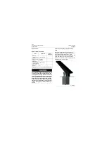
Accumulator assembly
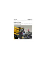
The accumulator assembly, which is located in
the housing at left side of complete machine and
is fixed on rear frame, mainly consists of service
brake accumulator and parking brake
accumulator, and the service brake accumulator
BR1 (front axle), service brake accumulator BR2
(rear axle) and parking brake accumulator BR3
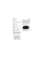
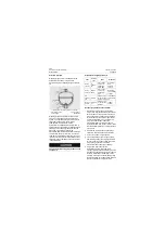
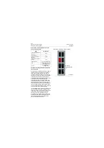
are installed as shown in figure. Installation
diagram is as follows:
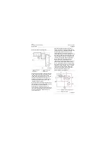
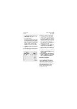
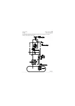
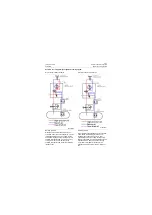
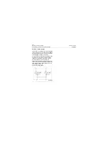
Oil line diagram in bypass state:
Shuttle valve is used to guarantee two brake
circuits are not in interference with each
other. When one of circuits fails and the pres-
sure decreases, the circuit is closed under
spring force. Make sure that the brake circuit
with zero-failure still realize braking function.
At this time, the failed circuit is connected
with the charge valve, the pressure of B3 port
decreases, low pressure alarm switch of ser-
vice brake acts, the machine shall be stopped
immediately for inspection.
P18H00047
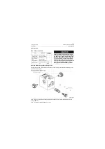
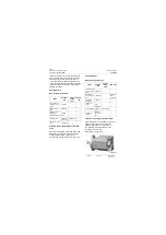
Installation diagram of accumulator
P18H00048
BR3
BR1
BR2
Содержание CLG835H
Страница 2: ......
Страница 4: ...Contents January 24 2017 CLG835H...
Страница 6: ...1 2 General Information January 24 2017 CLG835H...
Страница 38: ...1 34 Machine Inspection Table January 24 2017 CLG835H...
Страница 154: ...2 116 Fault Diagnosis and Troubleshooting January 24 2017 Common fault code and troubleshooting CLG835H...
Страница 156: ...3 2 Power Train System January 24 2017 CLG835H...
Страница 214: ...3 2 Power Train System January 24 2017 CLG835H...
Страница 272: ...3 60 Testing and adjustment January 24 2017 Power Train Test CLG835H...
Страница 276: ...4 4 Hydraulic System January 24 2017 CLG835H...
Страница 296: ...4 24 Structure Function Principle January 24 2017 Work hydraulic system CLG835H Exploded view of control valve P18H00016...
Страница 297: ...4 25 January 24 2017 Structure Function Principle CLG835H Work hydraulic system Exploded view of control valve P18H00017...
Страница 308: ...4 36 Structure Function Principle January 24 2017 Work hydraulic system CLG835H Outline diagram of pilot valve P18H00027...
Страница 506: ...4 234 Fault Diagnosis and Troubleshooting January 24 2017 Common troubleshooting for brake system CLG835H...
Страница 552: ...6 2 Driver s Cab System January 24 2017 CLG835H...
Страница 606: ...6 56 Removal and Installation January 24 2017 Removal and installation of the engine hood torque mechanism CLG835H...
Страница 608: ...7 2 Structure January 24 2017 CLG835H...
Страница 662: ...8 4 Electrical System January 24 2017 CLG835H...
Страница 677: ...8 19 January 24 2017 Structure Function Principle CLG835H Power System P18E00014...
Страница 737: ...8 79 January 24 2017 Structure Function Principle CLG835H Audio system Audio system Audio system principle P18E00138...
Страница 756: ...9 2 Appendix January 24 2017 CLG835H...
Страница 757: ...9 3 January 24 2017 Schematic Diagram of Hydraulic System CLG835H Schematic Diagram of Hydraulic System...
Страница 758: ...9 4 January 24 2017 Schematic Diagram of Brake System CLG835H Schematic Diagram of Brake System...

