8-25
January 24, 2017
Structure Function Principle
CLG835H
Starting module
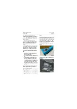
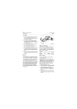
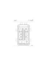
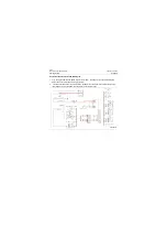
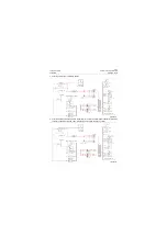
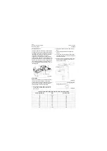
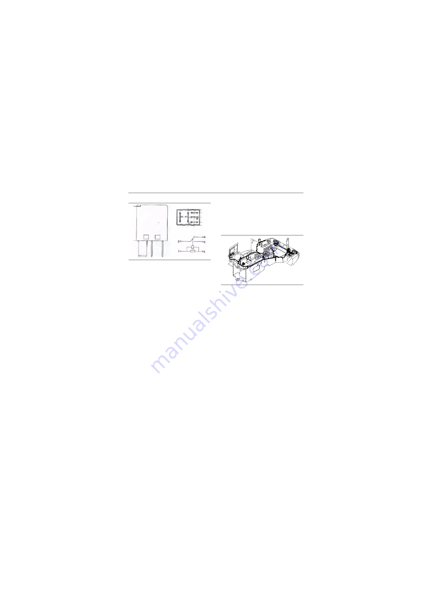
MINI relay is concentrated on the control box.
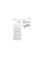
Steps of relay troubleshooting
1. Turn the digital multimeter to 200
Ω
of
Ω
posi-
tion.
2. Connect the red probe of DMM to the relay
terminal "1", while the black probe to terminal
"2", the value displayed on DMM shall be
around "155" thereby.
3. Connect the one probe of DMM to the relay
terminal "5", while the other to terminal "3",
the value displayed on DMM shall be "1"
thereby; change the probe on the terminal "5"
to the terminal "4" , the value displayed on
DMM shall be "0".
4. Apply +24V external power (+) to the terminal
"1" of relay, while (-) pole to terminal "2"; on
the other hand, connect one probe of DMM to
the terminal "5" of relay, the other probe to
terminal "3", thereby, the DMM displayed
value shall be "0". Shift the probe at terminal
"5" to terminal"4", the value displayed on
DMM shall be "1".
After completing the above steps, if the values
displayed on DMM conform to that described in
the steps, the relay is in good service condition.
The above steps are inapplicable to the operat-
ing contacts (both normally open and closed con-
tacts) where the abrasion is very severe.
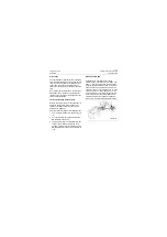
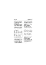
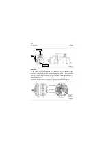
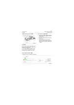
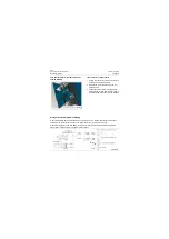
Starting Motor
The starter motor equipped in the machine is
configured for 24V/5.5kw. The DC motor within
the starter motor translates the electrical energy
of battery into mechanical energy, whereby the
internal transmission gear drives the motor fly-
wheel to start the engine.
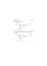
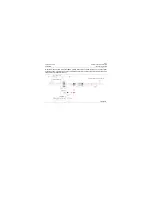
P18E00021
P18E00022
Содержание CLG835H
Страница 2: ......
Страница 4: ...Contents January 24 2017 CLG835H...
Страница 6: ...1 2 General Information January 24 2017 CLG835H...
Страница 38: ...1 34 Machine Inspection Table January 24 2017 CLG835H...
Страница 154: ...2 116 Fault Diagnosis and Troubleshooting January 24 2017 Common fault code and troubleshooting CLG835H...
Страница 156: ...3 2 Power Train System January 24 2017 CLG835H...
Страница 214: ...3 2 Power Train System January 24 2017 CLG835H...
Страница 272: ...3 60 Testing and adjustment January 24 2017 Power Train Test CLG835H...
Страница 276: ...4 4 Hydraulic System January 24 2017 CLG835H...
Страница 296: ...4 24 Structure Function Principle January 24 2017 Work hydraulic system CLG835H Exploded view of control valve P18H00016...
Страница 297: ...4 25 January 24 2017 Structure Function Principle CLG835H Work hydraulic system Exploded view of control valve P18H00017...
Страница 308: ...4 36 Structure Function Principle January 24 2017 Work hydraulic system CLG835H Outline diagram of pilot valve P18H00027...
Страница 506: ...4 234 Fault Diagnosis and Troubleshooting January 24 2017 Common troubleshooting for brake system CLG835H...
Страница 552: ...6 2 Driver s Cab System January 24 2017 CLG835H...
Страница 606: ...6 56 Removal and Installation January 24 2017 Removal and installation of the engine hood torque mechanism CLG835H...
Страница 608: ...7 2 Structure January 24 2017 CLG835H...
Страница 662: ...8 4 Electrical System January 24 2017 CLG835H...
Страница 677: ...8 19 January 24 2017 Structure Function Principle CLG835H Power System P18E00014...
Страница 737: ...8 79 January 24 2017 Structure Function Principle CLG835H Audio system Audio system Audio system principle P18E00138...
Страница 756: ...9 2 Appendix January 24 2017 CLG835H...
Страница 757: ...9 3 January 24 2017 Schematic Diagram of Hydraulic System CLG835H Schematic Diagram of Hydraulic System...
Страница 758: ...9 4 January 24 2017 Schematic Diagram of Brake System CLG835H Schematic Diagram of Brake System...


