4-50
Structure Function Principle
January 24, 2017
Brake system
CLG835H
Brake pump
Main technical parameters
Structure and working principle of brake
pump
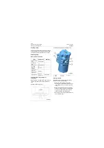
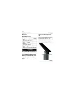
The brake pump is a gear pump and located
under cab and installed on the left power take-off
of the gearbox and tightened by stud and nut. It
is driven by engine via hydraulic torque converter
and gearbox to supply oil for brake hydraulic
system.
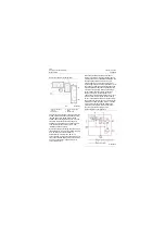
The gear pump works by using the meshing
movement of a pair of gears and causing volume
changes in the suction and discharge chambers.
It is the suction port with a closed volume always
in a growing state, and it is the outlet with a
closed volume always in an ever-reduced state.
Generally, the side with larger port is the suction
port, and the side with smaller port is the outlet.
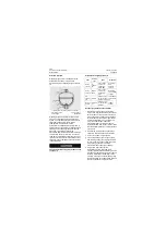
Overall structure of brake pump
Items
Parameters
Service
conditions
Theoretical
displacement (ml/r\cc/
r)
15\2175
/
Rated speed (r/min)
2200
/
Maximum speed (r/
min)
2500
/
Rated pressure
(Mpa\psi)
18\2610
/
Maximum
pressure(Mpa\psi)
25\3625
Volume efficiency
0.92
/
Operating fluid
Anti-wear
hydraulic oil
HM46/
HV46
Direction of rotation
Left rotation
/
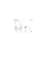
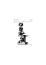
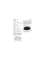
Gear pump working principle schematic
P18H00038
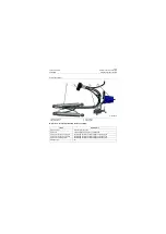
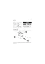
Schematic diagram of brake pump
1. Oil outlet (for oil entering into high-pressure oil filter)
2. Safety valve of brake system
3. Oil inlet (to oil outlet steel tube of tank)
P18H00039
1
2
3
Содержание CLG835H
Страница 2: ......
Страница 4: ...Contents January 24 2017 CLG835H...
Страница 6: ...1 2 General Information January 24 2017 CLG835H...
Страница 38: ...1 34 Machine Inspection Table January 24 2017 CLG835H...
Страница 154: ...2 116 Fault Diagnosis and Troubleshooting January 24 2017 Common fault code and troubleshooting CLG835H...
Страница 156: ...3 2 Power Train System January 24 2017 CLG835H...
Страница 214: ...3 2 Power Train System January 24 2017 CLG835H...
Страница 272: ...3 60 Testing and adjustment January 24 2017 Power Train Test CLG835H...
Страница 276: ...4 4 Hydraulic System January 24 2017 CLG835H...
Страница 296: ...4 24 Structure Function Principle January 24 2017 Work hydraulic system CLG835H Exploded view of control valve P18H00016...
Страница 297: ...4 25 January 24 2017 Structure Function Principle CLG835H Work hydraulic system Exploded view of control valve P18H00017...
Страница 308: ...4 36 Structure Function Principle January 24 2017 Work hydraulic system CLG835H Outline diagram of pilot valve P18H00027...
Страница 506: ...4 234 Fault Diagnosis and Troubleshooting January 24 2017 Common troubleshooting for brake system CLG835H...
Страница 552: ...6 2 Driver s Cab System January 24 2017 CLG835H...
Страница 606: ...6 56 Removal and Installation January 24 2017 Removal and installation of the engine hood torque mechanism CLG835H...
Страница 608: ...7 2 Structure January 24 2017 CLG835H...
Страница 662: ...8 4 Electrical System January 24 2017 CLG835H...
Страница 677: ...8 19 January 24 2017 Structure Function Principle CLG835H Power System P18E00014...
Страница 737: ...8 79 January 24 2017 Structure Function Principle CLG835H Audio system Audio system Audio system principle P18E00138...
Страница 756: ...9 2 Appendix January 24 2017 CLG835H...
Страница 757: ...9 3 January 24 2017 Schematic Diagram of Hydraulic System CLG835H Schematic Diagram of Hydraulic System...
Страница 758: ...9 4 January 24 2017 Schematic Diagram of Brake System CLG835H Schematic Diagram of Brake System...

