7-20
Removal and Installation
January 24, 2017
Removal and installation of counterweight assembly
CLG835H
Removal and installation of counterweight assembly
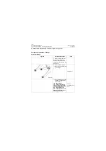
Removal of the left and right battery box (take left battery box as an example)
Removal description: Before removing left and right battery box, please remove cooling system, fuel
tank assembly and DEF lines assembly.
Figures
Operation instruction
Tools
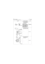
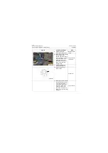
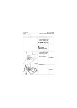
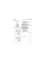
1. Remove rear floodlight and
battery, and please refer to
removal steps for rear flood-
light and battery of electrical
system.
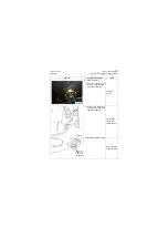
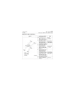
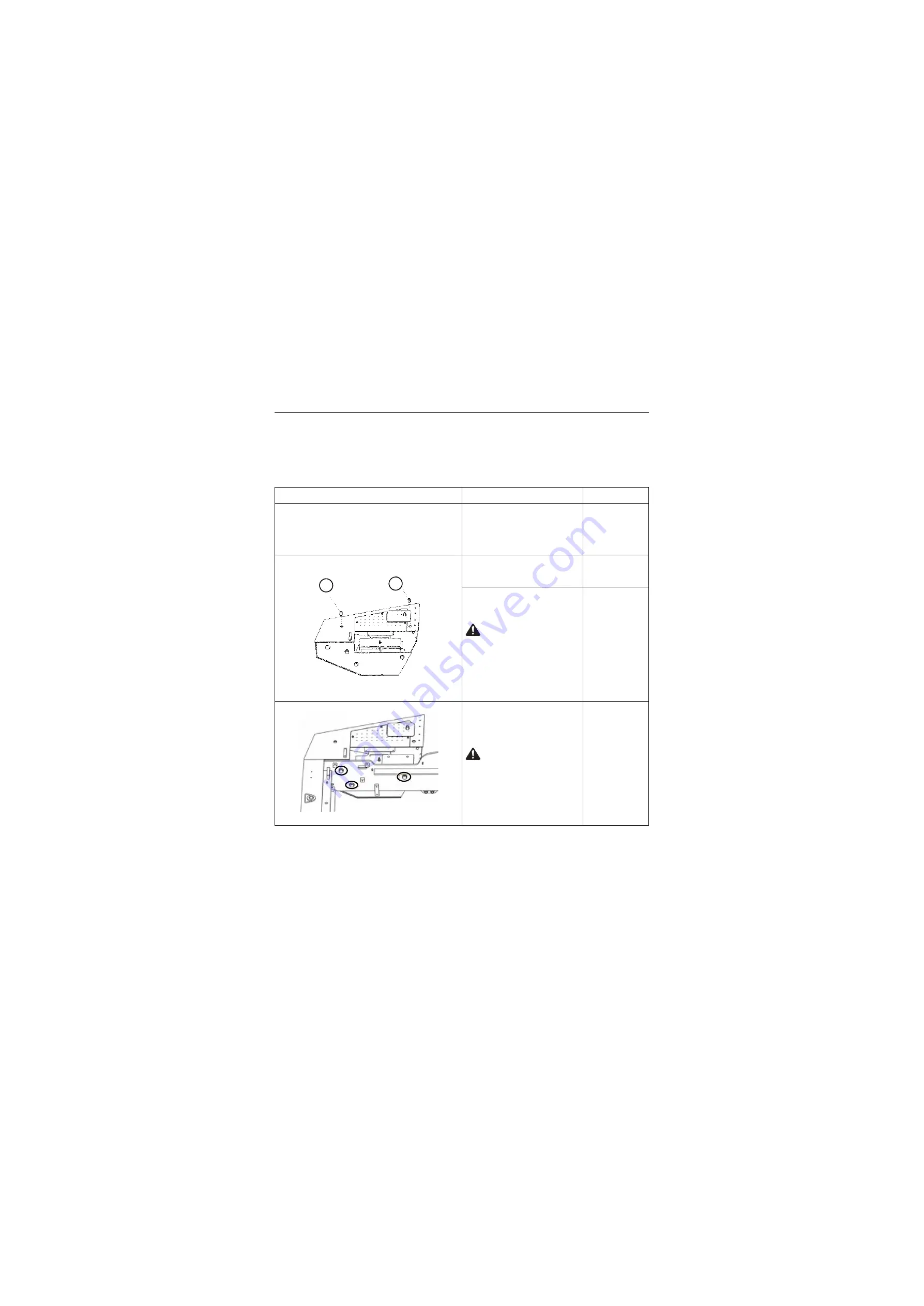
2. First take out plug (4), and
then install 2 M24 lifting
screws
Straight
screwdriver
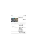
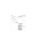
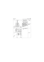
3. Hook the loop screw by a lift-
ing appliance and tighten
the hanger slightly
CAUTION: The
personnel operating
lifting equipment shall have
relevant qualifications, and
only can operate on the
premise that equipment and
lifting sling are normal and
safety is guaranteed!
Hoisting
equipment (over
3ton)
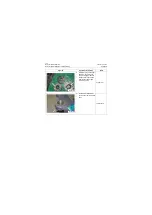
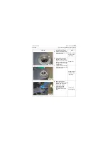
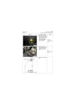
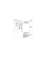
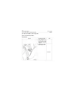
4. Remove 3 mounting bolts,
lift the counterweight out
with lifting equipment and
put on firm ground.
CAUTION: The
personnel operating
lifting equipment shall have
relevant qualifications, and
only can operate on the
premise that equipment and
lifting sling are normal and
safety is guaranteed!
36# socket
wrench, lifting
equipments
(over 3 tons)
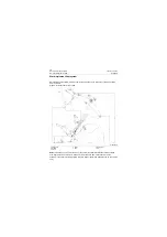
P18S00031
4
4
P18S00032
Содержание CLG835H
Страница 2: ......
Страница 4: ...Contents January 24 2017 CLG835H...
Страница 6: ...1 2 General Information January 24 2017 CLG835H...
Страница 38: ...1 34 Machine Inspection Table January 24 2017 CLG835H...
Страница 154: ...2 116 Fault Diagnosis and Troubleshooting January 24 2017 Common fault code and troubleshooting CLG835H...
Страница 156: ...3 2 Power Train System January 24 2017 CLG835H...
Страница 214: ...3 2 Power Train System January 24 2017 CLG835H...
Страница 272: ...3 60 Testing and adjustment January 24 2017 Power Train Test CLG835H...
Страница 276: ...4 4 Hydraulic System January 24 2017 CLG835H...
Страница 296: ...4 24 Structure Function Principle January 24 2017 Work hydraulic system CLG835H Exploded view of control valve P18H00016...
Страница 297: ...4 25 January 24 2017 Structure Function Principle CLG835H Work hydraulic system Exploded view of control valve P18H00017...
Страница 308: ...4 36 Structure Function Principle January 24 2017 Work hydraulic system CLG835H Outline diagram of pilot valve P18H00027...
Страница 506: ...4 234 Fault Diagnosis and Troubleshooting January 24 2017 Common troubleshooting for brake system CLG835H...
Страница 552: ...6 2 Driver s Cab System January 24 2017 CLG835H...
Страница 606: ...6 56 Removal and Installation January 24 2017 Removal and installation of the engine hood torque mechanism CLG835H...
Страница 608: ...7 2 Structure January 24 2017 CLG835H...
Страница 662: ...8 4 Electrical System January 24 2017 CLG835H...
Страница 677: ...8 19 January 24 2017 Structure Function Principle CLG835H Power System P18E00014...
Страница 737: ...8 79 January 24 2017 Structure Function Principle CLG835H Audio system Audio system Audio system principle P18E00138...
Страница 756: ...9 2 Appendix January 24 2017 CLG835H...
Страница 757: ...9 3 January 24 2017 Schematic Diagram of Hydraulic System CLG835H Schematic Diagram of Hydraulic System...
Страница 758: ...9 4 January 24 2017 Schematic Diagram of Brake System CLG835H Schematic Diagram of Brake System...

