8-15
January 24, 2017
Structure Function Principle
CLG835H
Power System
Precautions
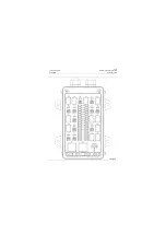
The specifications of different fuses are available
from calculation during the circuit design, accord-
ingly, the blown fuse shall be replaced with that
of the same series and specifications. Don’t
replace the fuse with a fuse of different specifica-
tions.
On condition that the replacement of blown fuse
break down again, proceed on replacing after
inspecting the circuit under the jurisdiction of the
fuse and troubleshooting.
The troubleshooting method of fuse
Remove the plug-in fuse from the fuse holder, to
determine the condition of fuse visually. The
inspection methods of bolt fuses can also be
applied in the judgment.
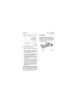
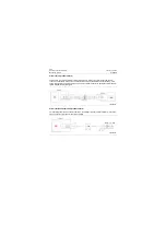
Adjustment steps for blowout of bolting type fuse:
1. Turn the digital multimeter to 200
Ω
of
Ω
posi-
tion.
2. Connect both terminals of the fuse with the
DMM probes respectively.
3. The indicated value "1" of the DMM signifies
that the fuse is blown and replacement is
needed, while the value "0" displayed on the
DMM indicates the good service condition of
fuse.
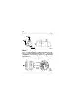
Disconnect switch
Negative switch regulates the connection
between battery (-) and the machine frame. The
power (-) of the whole machine is disconnected
when the negative switch is turned to "O" (OFF).
The complete vehicle electrical equipment can-
not work even turn on the electrical lock. Turn the
negative switch to "I" (ON), the power (-) of the
whole machine is connected. Whereby, the elec-
tric lock controls the connections between the
electrical components and powers throughout
the machine, as well as starts the diesel engine.
P18E00010
Содержание CLG835H
Страница 2: ......
Страница 4: ...Contents January 24 2017 CLG835H...
Страница 6: ...1 2 General Information January 24 2017 CLG835H...
Страница 38: ...1 34 Machine Inspection Table January 24 2017 CLG835H...
Страница 154: ...2 116 Fault Diagnosis and Troubleshooting January 24 2017 Common fault code and troubleshooting CLG835H...
Страница 156: ...3 2 Power Train System January 24 2017 CLG835H...
Страница 214: ...3 2 Power Train System January 24 2017 CLG835H...
Страница 272: ...3 60 Testing and adjustment January 24 2017 Power Train Test CLG835H...
Страница 276: ...4 4 Hydraulic System January 24 2017 CLG835H...
Страница 296: ...4 24 Structure Function Principle January 24 2017 Work hydraulic system CLG835H Exploded view of control valve P18H00016...
Страница 297: ...4 25 January 24 2017 Structure Function Principle CLG835H Work hydraulic system Exploded view of control valve P18H00017...
Страница 308: ...4 36 Structure Function Principle January 24 2017 Work hydraulic system CLG835H Outline diagram of pilot valve P18H00027...
Страница 506: ...4 234 Fault Diagnosis and Troubleshooting January 24 2017 Common troubleshooting for brake system CLG835H...
Страница 552: ...6 2 Driver s Cab System January 24 2017 CLG835H...
Страница 606: ...6 56 Removal and Installation January 24 2017 Removal and installation of the engine hood torque mechanism CLG835H...
Страница 608: ...7 2 Structure January 24 2017 CLG835H...
Страница 662: ...8 4 Electrical System January 24 2017 CLG835H...
Страница 677: ...8 19 January 24 2017 Structure Function Principle CLG835H Power System P18E00014...
Страница 737: ...8 79 January 24 2017 Structure Function Principle CLG835H Audio system Audio system Audio system principle P18E00138...
Страница 756: ...9 2 Appendix January 24 2017 CLG835H...
Страница 757: ...9 3 January 24 2017 Schematic Diagram of Hydraulic System CLG835H Schematic Diagram of Hydraulic System...
Страница 758: ...9 4 January 24 2017 Schematic Diagram of Brake System CLG835H Schematic Diagram of Brake System...

