8-26
Structure Function Principle
January 24, 2017
Starting module
CLG835H
Alternator
As the main power unit of the machine, the alternator translates the energy from diesel engine into ser-
viceable electric energy of electrical equipment. The electrical components are configured for 24V/100A,
with electronic voltage regulator equipped inside. The alternator is connected in parallel with the battery
to power the machine. The battery supplies power to the electrical components before the diesel engine
starts; then after it starts, alternator powers the electrical components while charging the battery. Once
the energy of alternator fails to meet the needs of the electrical components, the alternator and battery
jointly power the machine.
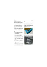
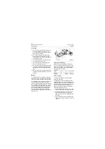
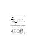
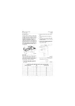
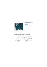
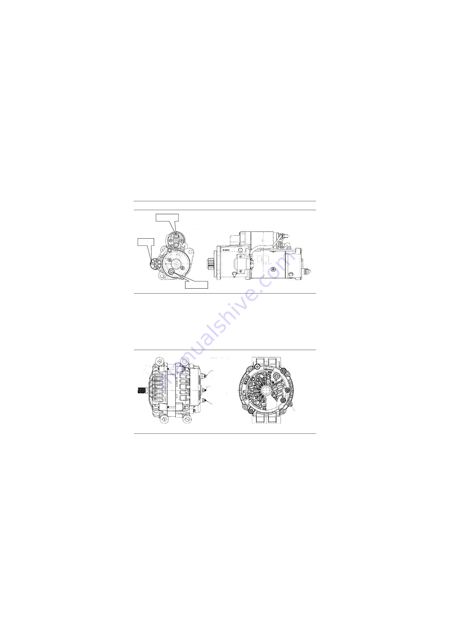
This machine uses three terminals of generator, i,e. 1. Battery Positive
;
2. Ground
;
3.LAMP (D+).
After #460
Connect with
the cable (-)
Connect
positive cable
P18E00023
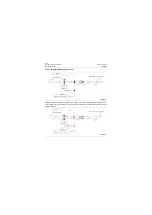
P18E00024
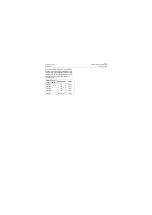
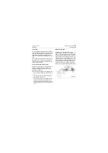
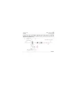
M8×1.25 THREAD
BATTERY TERMINAL
M5×0.8 THREAD
LAMP TERMINAL
M5×0.8 THREAD
PHASE TERMINAL
M6×1.0
THREAD
GROUND
TERMINAL
Содержание CLG835H
Страница 2: ......
Страница 4: ...Contents January 24 2017 CLG835H...
Страница 6: ...1 2 General Information January 24 2017 CLG835H...
Страница 38: ...1 34 Machine Inspection Table January 24 2017 CLG835H...
Страница 154: ...2 116 Fault Diagnosis and Troubleshooting January 24 2017 Common fault code and troubleshooting CLG835H...
Страница 156: ...3 2 Power Train System January 24 2017 CLG835H...
Страница 214: ...3 2 Power Train System January 24 2017 CLG835H...
Страница 272: ...3 60 Testing and adjustment January 24 2017 Power Train Test CLG835H...
Страница 276: ...4 4 Hydraulic System January 24 2017 CLG835H...
Страница 296: ...4 24 Structure Function Principle January 24 2017 Work hydraulic system CLG835H Exploded view of control valve P18H00016...
Страница 297: ...4 25 January 24 2017 Structure Function Principle CLG835H Work hydraulic system Exploded view of control valve P18H00017...
Страница 308: ...4 36 Structure Function Principle January 24 2017 Work hydraulic system CLG835H Outline diagram of pilot valve P18H00027...
Страница 506: ...4 234 Fault Diagnosis and Troubleshooting January 24 2017 Common troubleshooting for brake system CLG835H...
Страница 552: ...6 2 Driver s Cab System January 24 2017 CLG835H...
Страница 606: ...6 56 Removal and Installation January 24 2017 Removal and installation of the engine hood torque mechanism CLG835H...
Страница 608: ...7 2 Structure January 24 2017 CLG835H...
Страница 662: ...8 4 Electrical System January 24 2017 CLG835H...
Страница 677: ...8 19 January 24 2017 Structure Function Principle CLG835H Power System P18E00014...
Страница 737: ...8 79 January 24 2017 Structure Function Principle CLG835H Audio system Audio system Audio system principle P18E00138...
Страница 756: ...9 2 Appendix January 24 2017 CLG835H...
Страница 757: ...9 3 January 24 2017 Schematic Diagram of Hydraulic System CLG835H Schematic Diagram of Hydraulic System...
Страница 758: ...9 4 January 24 2017 Schematic Diagram of Brake System CLG835H Schematic Diagram of Brake System...

