4-121
January 24, 2017
Removal and Installation
CLG835H
Work hydraulic system
Removal steps
Figures
Operation instruction
Tools
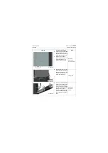
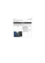
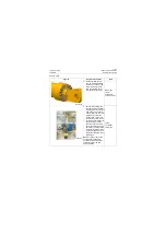
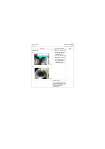
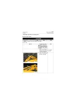
1. Loosen the 12 M16×70-
10.9-Zn.D bolts diagonally
(as shown by arrows in fig-
ure) with blower gun and
then remove them one by
one together with washer.
Blower gun
Link for
assembling
14mm hex bolt
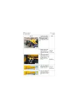
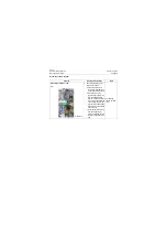
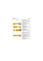
2. Put one end of lifting rope
through the piston rod dual
lug (single lug for bucket cyl-
inder ) and fix it crosswise
with the other end on the lift-
ing equipment, and then
conduct slow, uniform and
vertical lifting, place the pis-
ton rod group horizontally on
special working position
apparatus after it (see left
figure) separates from cylin-
der block completely (Note:
the contact surface of work-
ing position apparatus and
the cylinder shall be made of
soft material.
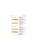
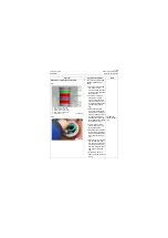
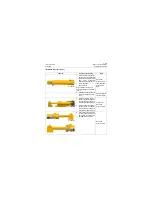
Note:
Put clean cotton on the
contact surface of working
position apparatus and piston
rod to prevent the rod from
being scratched.
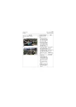
Lifting
equipment
Lifting rope
P18H00152
P18H00153
Содержание CLG835H
Страница 2: ......
Страница 4: ...Contents January 24 2017 CLG835H...
Страница 6: ...1 2 General Information January 24 2017 CLG835H...
Страница 38: ...1 34 Machine Inspection Table January 24 2017 CLG835H...
Страница 154: ...2 116 Fault Diagnosis and Troubleshooting January 24 2017 Common fault code and troubleshooting CLG835H...
Страница 156: ...3 2 Power Train System January 24 2017 CLG835H...
Страница 214: ...3 2 Power Train System January 24 2017 CLG835H...
Страница 272: ...3 60 Testing and adjustment January 24 2017 Power Train Test CLG835H...
Страница 276: ...4 4 Hydraulic System January 24 2017 CLG835H...
Страница 296: ...4 24 Structure Function Principle January 24 2017 Work hydraulic system CLG835H Exploded view of control valve P18H00016...
Страница 297: ...4 25 January 24 2017 Structure Function Principle CLG835H Work hydraulic system Exploded view of control valve P18H00017...
Страница 308: ...4 36 Structure Function Principle January 24 2017 Work hydraulic system CLG835H Outline diagram of pilot valve P18H00027...
Страница 506: ...4 234 Fault Diagnosis and Troubleshooting January 24 2017 Common troubleshooting for brake system CLG835H...
Страница 552: ...6 2 Driver s Cab System January 24 2017 CLG835H...
Страница 606: ...6 56 Removal and Installation January 24 2017 Removal and installation of the engine hood torque mechanism CLG835H...
Страница 608: ...7 2 Structure January 24 2017 CLG835H...
Страница 662: ...8 4 Electrical System January 24 2017 CLG835H...
Страница 677: ...8 19 January 24 2017 Structure Function Principle CLG835H Power System P18E00014...
Страница 737: ...8 79 January 24 2017 Structure Function Principle CLG835H Audio system Audio system Audio system principle P18E00138...
Страница 756: ...9 2 Appendix January 24 2017 CLG835H...
Страница 757: ...9 3 January 24 2017 Schematic Diagram of Hydraulic System CLG835H Schematic Diagram of Hydraulic System...
Страница 758: ...9 4 January 24 2017 Schematic Diagram of Brake System CLG835H Schematic Diagram of Brake System...

