2-25
January 24, 2017
Structure Function Principle
CLG835H
Intake and exhaust system
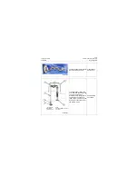
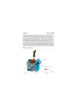
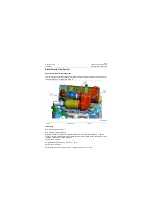
Working principle of the intake and exhaust assembly: air is taken in through air pre-filter. There are
rotating blades inside the air pre-filter, which can discharge big dust in intake air from the bottom of air
pre-filter. Intake air reaches air filter, filter element removes small dust and moisture to obtain clean and
dry air to be sent to turbocharger, the turbocharger is driven by engine exhaust to pressurize intake air
and increase intake quantity, and sufficient combustion of fuel can be ensured. Air coming out of turbo-
charger goes through air-air intercooler in cooling system and electric heater of engine itself to obtain
proper temperature and then enters engine block to burn. Exhaust gas generated after combustion
reaches turbocharger via exhaust manifold, drives turbocharger to pressurize intake air and is then dis-
charged to DPF (Diesel Particle Filter). When exhaust gas gets to diesel particle filter DOC, particulates
will be oxidized to CO2. Then enters into decomposition reactor tube (DRT). Urea solution injected to
DRT from the outside will break down to form ammonia gas and mingle with exhaust gas. When gas
mixture including exhaust gas and ammonia gas enters into diesel particle filter SCR, under the reaction
of catalyzer, nitride oxides will be broken down into nitrogen and water. Finally, exhaust gas pollutants
content injected into the atmosphere will be greatly reduced, conforming with Euro IV emission require-
ment.
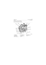
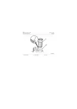
Air intake path figure of engine:
1. Air pre-filter
2. Air filter
3. Turbocharger
Hot gas
Cold gas
P18P00033
2
1
3
Содержание CLG835H
Страница 2: ......
Страница 4: ...Contents January 24 2017 CLG835H...
Страница 6: ...1 2 General Information January 24 2017 CLG835H...
Страница 38: ...1 34 Machine Inspection Table January 24 2017 CLG835H...
Страница 154: ...2 116 Fault Diagnosis and Troubleshooting January 24 2017 Common fault code and troubleshooting CLG835H...
Страница 156: ...3 2 Power Train System January 24 2017 CLG835H...
Страница 214: ...3 2 Power Train System January 24 2017 CLG835H...
Страница 272: ...3 60 Testing and adjustment January 24 2017 Power Train Test CLG835H...
Страница 276: ...4 4 Hydraulic System January 24 2017 CLG835H...
Страница 296: ...4 24 Structure Function Principle January 24 2017 Work hydraulic system CLG835H Exploded view of control valve P18H00016...
Страница 297: ...4 25 January 24 2017 Structure Function Principle CLG835H Work hydraulic system Exploded view of control valve P18H00017...
Страница 308: ...4 36 Structure Function Principle January 24 2017 Work hydraulic system CLG835H Outline diagram of pilot valve P18H00027...
Страница 506: ...4 234 Fault Diagnosis and Troubleshooting January 24 2017 Common troubleshooting for brake system CLG835H...
Страница 552: ...6 2 Driver s Cab System January 24 2017 CLG835H...
Страница 606: ...6 56 Removal and Installation January 24 2017 Removal and installation of the engine hood torque mechanism CLG835H...
Страница 608: ...7 2 Structure January 24 2017 CLG835H...
Страница 662: ...8 4 Electrical System January 24 2017 CLG835H...
Страница 677: ...8 19 January 24 2017 Structure Function Principle CLG835H Power System P18E00014...
Страница 737: ...8 79 January 24 2017 Structure Function Principle CLG835H Audio system Audio system Audio system principle P18E00138...
Страница 756: ...9 2 Appendix January 24 2017 CLG835H...
Страница 757: ...9 3 January 24 2017 Schematic Diagram of Hydraulic System CLG835H Schematic Diagram of Hydraulic System...
Страница 758: ...9 4 January 24 2017 Schematic Diagram of Brake System CLG835H Schematic Diagram of Brake System...


