8-7
January 24, 2017
Basic Information
CLG835H
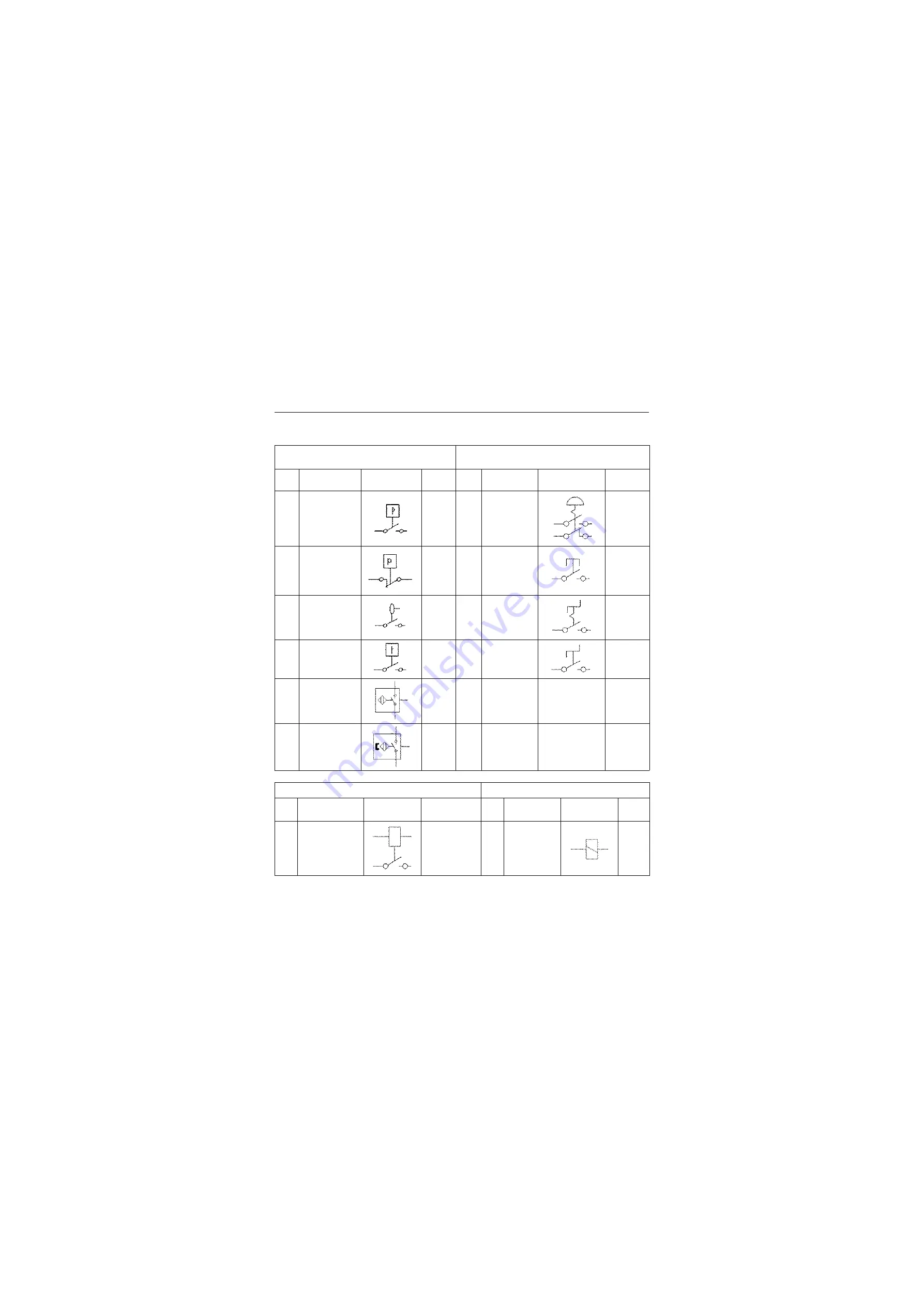
The introduction of signs on the electrical schematic
The introduction of signs on the electrical schematic
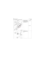
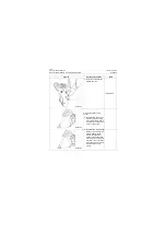
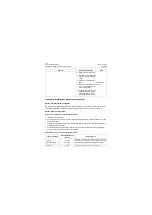
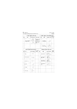
Graphic symbol of the control switch
Graphic symbol of double position manual
control switch
S/N
Name
Graphic symbol
Descrip-
tion
S/N
Name
Graphic symbol
Description
1
Pressure switch
Normally
open
1
Emergency stop
switch
Keeping
2
Pressure switch
Normally
closed
2
Button switch
Instanta-
neous acting
3
Temperature
switch
3
Knob switch
Keeping
4
Liquid level switch
4
Knob switch
Instanta-
neous acting
5
Induction proxim-
ity switch
6
Magnetic induc-
tion proximity
switch
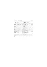
Graphic symbol of the relay
Graphic symbol of the electromagnet
S/N
Name
Graphic symbol
Description
S/N
Name
Graphic symbol
Descrip
tion
1
GP relay
One group of
normally-open
contacts
1
Electromagnet
of the switch
Содержание CLG835H
Страница 2: ......
Страница 4: ...Contents January 24 2017 CLG835H...
Страница 6: ...1 2 General Information January 24 2017 CLG835H...
Страница 38: ...1 34 Machine Inspection Table January 24 2017 CLG835H...
Страница 154: ...2 116 Fault Diagnosis and Troubleshooting January 24 2017 Common fault code and troubleshooting CLG835H...
Страница 156: ...3 2 Power Train System January 24 2017 CLG835H...
Страница 214: ...3 2 Power Train System January 24 2017 CLG835H...
Страница 272: ...3 60 Testing and adjustment January 24 2017 Power Train Test CLG835H...
Страница 276: ...4 4 Hydraulic System January 24 2017 CLG835H...
Страница 296: ...4 24 Structure Function Principle January 24 2017 Work hydraulic system CLG835H Exploded view of control valve P18H00016...
Страница 297: ...4 25 January 24 2017 Structure Function Principle CLG835H Work hydraulic system Exploded view of control valve P18H00017...
Страница 308: ...4 36 Structure Function Principle January 24 2017 Work hydraulic system CLG835H Outline diagram of pilot valve P18H00027...
Страница 506: ...4 234 Fault Diagnosis and Troubleshooting January 24 2017 Common troubleshooting for brake system CLG835H...
Страница 552: ...6 2 Driver s Cab System January 24 2017 CLG835H...
Страница 606: ...6 56 Removal and Installation January 24 2017 Removal and installation of the engine hood torque mechanism CLG835H...
Страница 608: ...7 2 Structure January 24 2017 CLG835H...
Страница 662: ...8 4 Electrical System January 24 2017 CLG835H...
Страница 677: ...8 19 January 24 2017 Structure Function Principle CLG835H Power System P18E00014...
Страница 737: ...8 79 January 24 2017 Structure Function Principle CLG835H Audio system Audio system Audio system principle P18E00138...
Страница 756: ...9 2 Appendix January 24 2017 CLG835H...
Страница 757: ...9 3 January 24 2017 Schematic Diagram of Hydraulic System CLG835H Schematic Diagram of Hydraulic System...
Страница 758: ...9 4 January 24 2017 Schematic Diagram of Brake System CLG835H Schematic Diagram of Brake System...


