8-11
January 24, 2017
Structure Function Principle
CLG835H
Power System
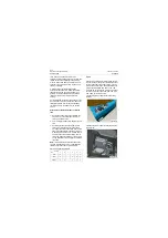
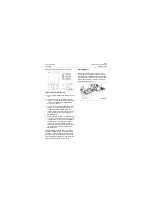
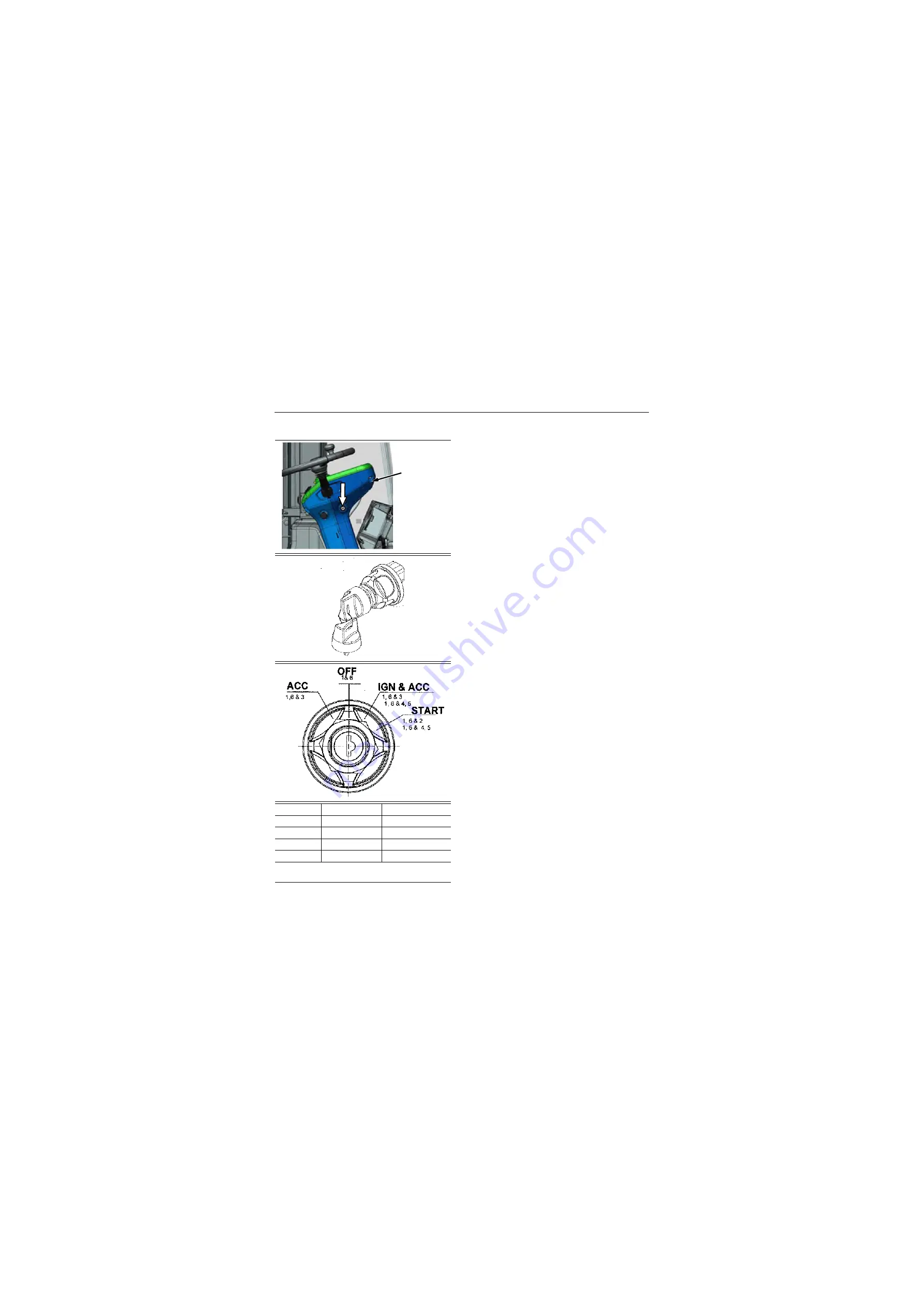
Electric lock
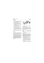
Description of pin definition:
Pins 1, 2, 3, 4, 5, 6;
The pins 3, 5 are normally not used;
Pins 1 and 6 - power supply, pin 4 - ignition (con-
trol power relay coil), pin 2 - starter;
Specification of the positions of the electric
lock
"OFF"-the position to insert and extract the
electrical lock key. At this gear, cut off the power
the electrical equipment on the vehicle. Except
for some electrical equipment (such as dome
light), which are controlled by the battery
disconnect switch instead of the electric lock.
"IGN"-the first gear of the clockwise rotating key
after inserting the key to electric lock. "IGN"
connects the powers of electrical equipment
throughout the machine, which are powered by
battery.
"START"-the second gear of the clockwise
rotating key after inserting the key to electric
lock. Such gear starts the diesel engine, which is
incapable of self-hold. The key to electric lock
returns automatically to "IGN" once it is
loosened.
Precautions
After starting the oil engine, loosen the key of the
electrical lock immediately to make it return to its
position. Otherwise it will lead to serious
electrical fault.
Switch off the electric lock if it fails to start for the
first time, then proceed on to second starts. First
turn the electrical lock key to "OFF" position.
Second turn it to the "IGN" position; Finally to
"START" position, which completes a startup
circle.
If the diesel engine fails to start within 15S,
switch off the electric lock. Continual starting
should be less than three times. Each start time
shall be controlled within 15S, or else power loss
may be resulted in for the continuous high-power
output of battery.
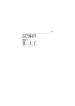
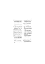
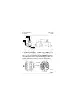
PIN
CIRCUIT
2
START
3
ACCESSARY
4&5
IGNITION
1&6
BATTERY
PINS 1&6 CONNECTED TOGETHER INTERNALLY
PINS 4&5 CONNECTED TOGETHER INTERNALLY
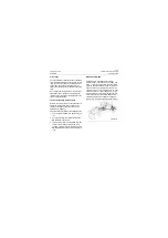
Steering
column
P18E00004
P18E00005
P18E00006
Содержание CLG835H
Страница 2: ......
Страница 4: ...Contents January 24 2017 CLG835H...
Страница 6: ...1 2 General Information January 24 2017 CLG835H...
Страница 38: ...1 34 Machine Inspection Table January 24 2017 CLG835H...
Страница 154: ...2 116 Fault Diagnosis and Troubleshooting January 24 2017 Common fault code and troubleshooting CLG835H...
Страница 156: ...3 2 Power Train System January 24 2017 CLG835H...
Страница 214: ...3 2 Power Train System January 24 2017 CLG835H...
Страница 272: ...3 60 Testing and adjustment January 24 2017 Power Train Test CLG835H...
Страница 276: ...4 4 Hydraulic System January 24 2017 CLG835H...
Страница 296: ...4 24 Structure Function Principle January 24 2017 Work hydraulic system CLG835H Exploded view of control valve P18H00016...
Страница 297: ...4 25 January 24 2017 Structure Function Principle CLG835H Work hydraulic system Exploded view of control valve P18H00017...
Страница 308: ...4 36 Structure Function Principle January 24 2017 Work hydraulic system CLG835H Outline diagram of pilot valve P18H00027...
Страница 506: ...4 234 Fault Diagnosis and Troubleshooting January 24 2017 Common troubleshooting for brake system CLG835H...
Страница 552: ...6 2 Driver s Cab System January 24 2017 CLG835H...
Страница 606: ...6 56 Removal and Installation January 24 2017 Removal and installation of the engine hood torque mechanism CLG835H...
Страница 608: ...7 2 Structure January 24 2017 CLG835H...
Страница 662: ...8 4 Electrical System January 24 2017 CLG835H...
Страница 677: ...8 19 January 24 2017 Structure Function Principle CLG835H Power System P18E00014...
Страница 737: ...8 79 January 24 2017 Structure Function Principle CLG835H Audio system Audio system Audio system principle P18E00138...
Страница 756: ...9 2 Appendix January 24 2017 CLG835H...
Страница 757: ...9 3 January 24 2017 Schematic Diagram of Hydraulic System CLG835H Schematic Diagram of Hydraulic System...
Страница 758: ...9 4 January 24 2017 Schematic Diagram of Brake System CLG835H Schematic Diagram of Brake System...


