8-33
January 24, 2017
Structure Function Principle
CLG835H
Monitoring system
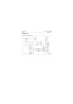
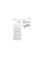
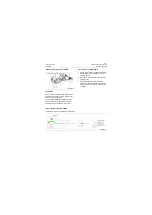
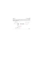
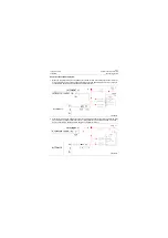
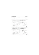
Circuit for DEF level indication
It is used for monitoring the liquid level of DEF pot. This machine uses Perkins Electric Injection Engine
whose ECM sends the DEF liquid level signal to the meter by CAN bus. The meter microcontroller pro-
cesses information after reading liquid level data, and finally to actuate the DEF liquid level gauge.
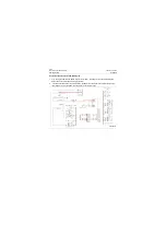
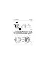
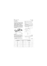
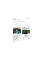
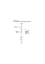
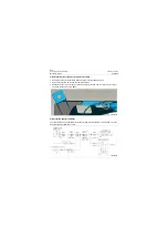
Circuit for vehicle speed indication
For monitoring the machine speed condition. The output speed sensor, installed on the gearbox housing,
is used to detect the speed of gearbox output gear. The speed sensor consists of coil, permanent mag-
net and pole. The coil is wound outside the pole, and the pole is connected with the permanent magnet.
The magnetic field is formed around the permanent magnet, magnetic lines of force pass through air gap
and act on the teeth of gear, forming a closed magnetic circuit. When the gear is rotating, the magnetic
field acts on the tooth gap and tooth repeatedly, so the change in air gap is sometimes big and some-
times small; the flux changes with the air gap, and the changing flux induces sinusoidal signal in the coil,
which is in proportion to speed. Connect to ZF harness, followed by being processed in the electrical
control unit, the processed signal therefrom is sent to the instrument.
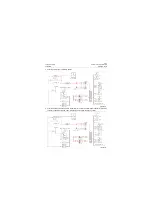
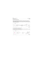
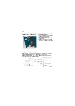
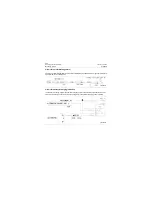
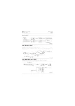
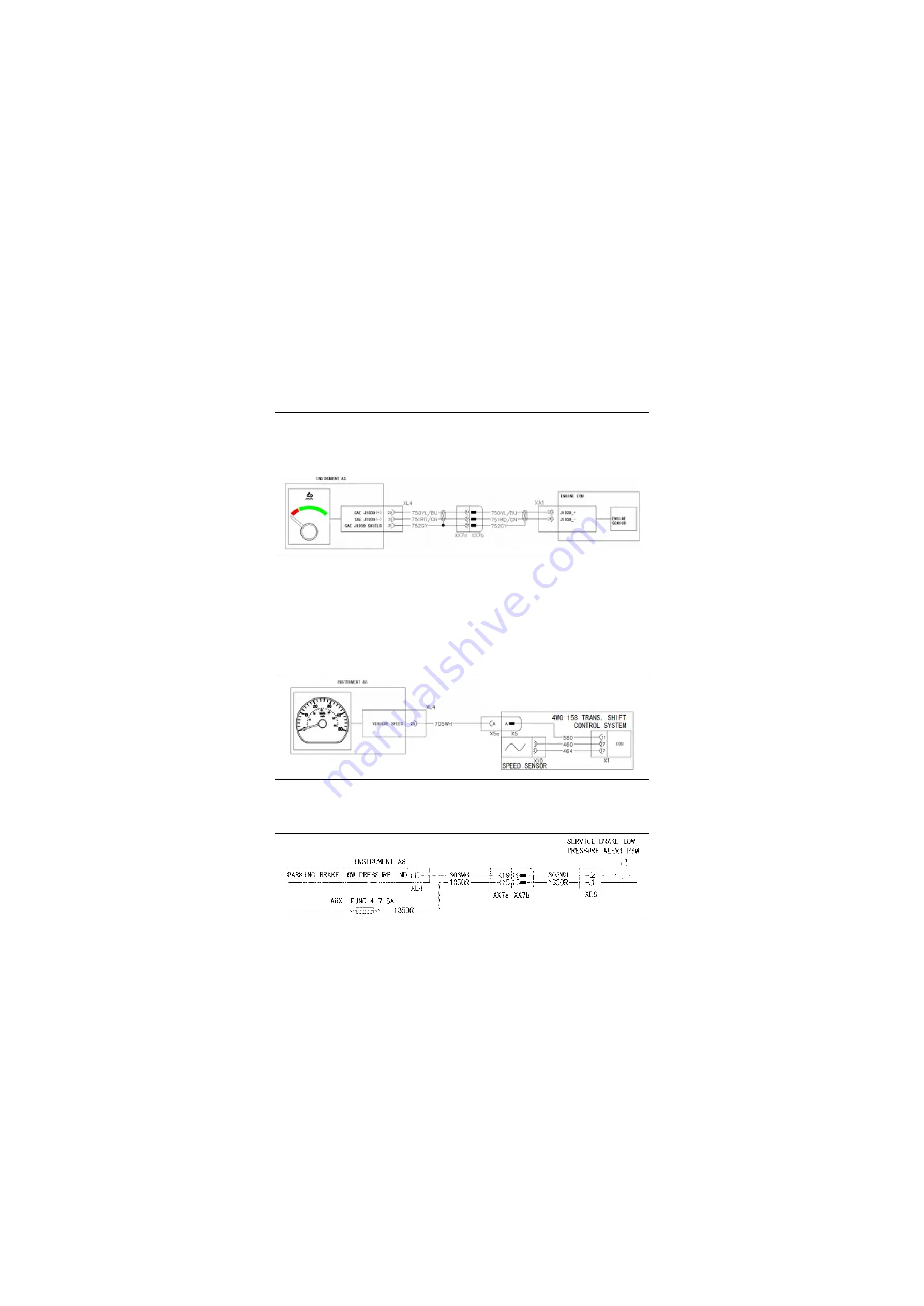
Service brake indication circuit
When sercive brake pressure is less than 9MPa, the pressure switch turns on and brake low pressure
indicator turns on.
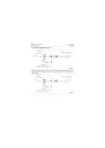
P18E00035
P18E00036
P18E00037
Содержание CLG835H
Страница 2: ......
Страница 4: ...Contents January 24 2017 CLG835H...
Страница 6: ...1 2 General Information January 24 2017 CLG835H...
Страница 38: ...1 34 Machine Inspection Table January 24 2017 CLG835H...
Страница 154: ...2 116 Fault Diagnosis and Troubleshooting January 24 2017 Common fault code and troubleshooting CLG835H...
Страница 156: ...3 2 Power Train System January 24 2017 CLG835H...
Страница 214: ...3 2 Power Train System January 24 2017 CLG835H...
Страница 272: ...3 60 Testing and adjustment January 24 2017 Power Train Test CLG835H...
Страница 276: ...4 4 Hydraulic System January 24 2017 CLG835H...
Страница 296: ...4 24 Structure Function Principle January 24 2017 Work hydraulic system CLG835H Exploded view of control valve P18H00016...
Страница 297: ...4 25 January 24 2017 Structure Function Principle CLG835H Work hydraulic system Exploded view of control valve P18H00017...
Страница 308: ...4 36 Structure Function Principle January 24 2017 Work hydraulic system CLG835H Outline diagram of pilot valve P18H00027...
Страница 506: ...4 234 Fault Diagnosis and Troubleshooting January 24 2017 Common troubleshooting for brake system CLG835H...
Страница 552: ...6 2 Driver s Cab System January 24 2017 CLG835H...
Страница 606: ...6 56 Removal and Installation January 24 2017 Removal and installation of the engine hood torque mechanism CLG835H...
Страница 608: ...7 2 Structure January 24 2017 CLG835H...
Страница 662: ...8 4 Electrical System January 24 2017 CLG835H...
Страница 677: ...8 19 January 24 2017 Structure Function Principle CLG835H Power System P18E00014...
Страница 737: ...8 79 January 24 2017 Structure Function Principle CLG835H Audio system Audio system Audio system principle P18E00138...
Страница 756: ...9 2 Appendix January 24 2017 CLG835H...
Страница 757: ...9 3 January 24 2017 Schematic Diagram of Hydraulic System CLG835H Schematic Diagram of Hydraulic System...
Страница 758: ...9 4 January 24 2017 Schematic Diagram of Brake System CLG835H Schematic Diagram of Brake System...

