2-33
January 24, 2017
Structure Function Principle
CLG835H
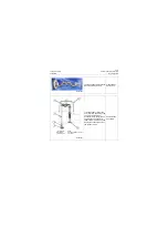
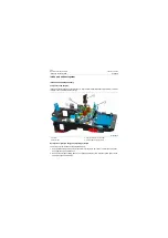
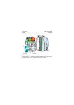
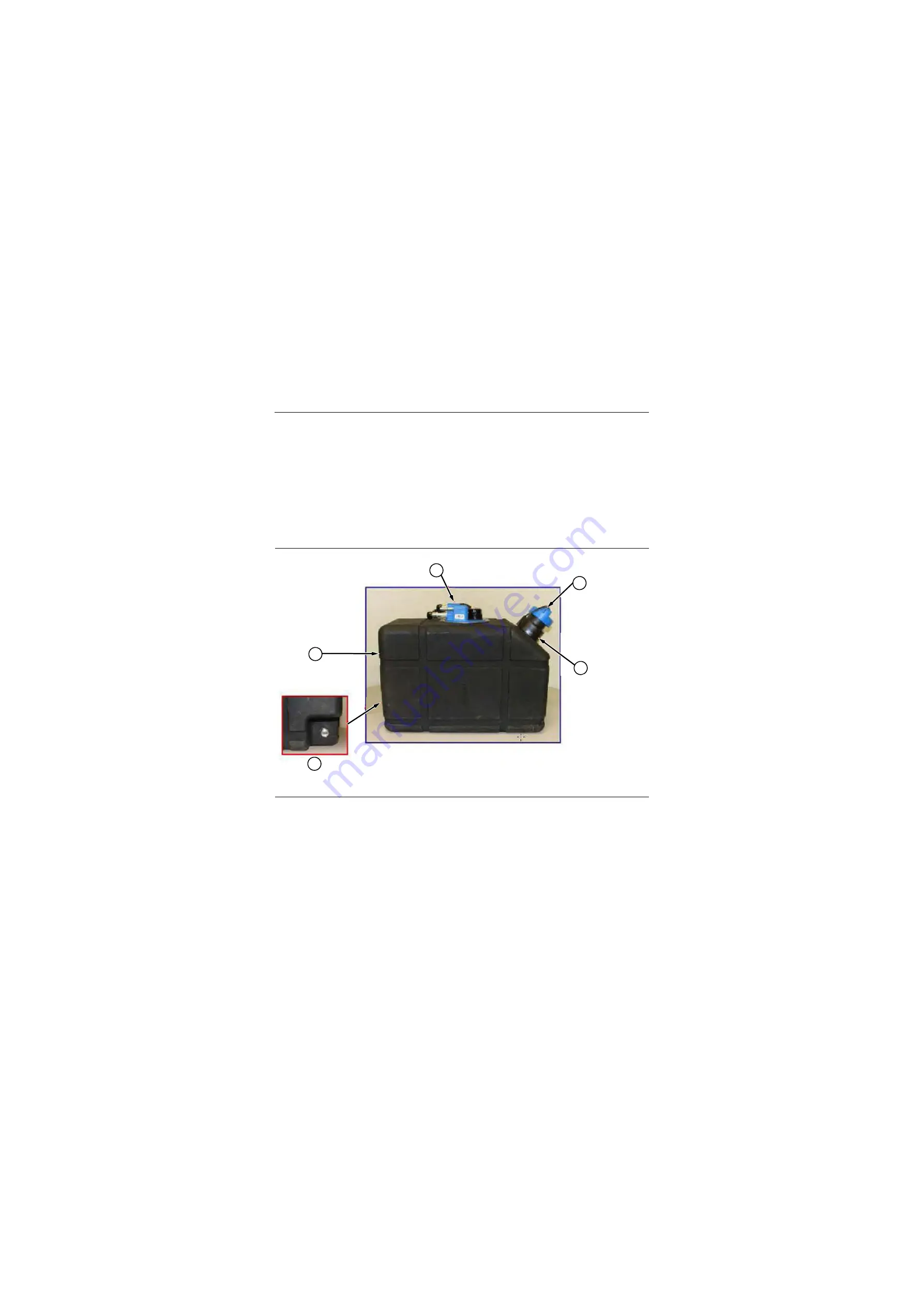
DEF pipeline assembly
Part Structure and Principle Introduction
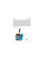
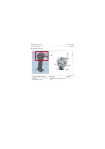
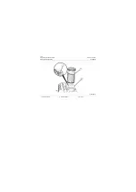
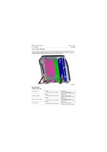
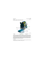
The function of DEF tank is to store DEF solution and provide DEF for DPF (Diesel Particle Filter) during
the machine operates. DEF tank consists of shell, multi-functional head unit and cover. There are three
sensors in the multi-functional head unit: temperature sensor, liquid level sensor and quality sensor.
Temperature sensor detects DEF solution temperature and transports signal to ECM, when DEF temper-
ature is less than -8°C, the solenoid water valve is opened, and engine coolant enters into def tank to
prevent DEF solution from freezing, however, when DEF temperature exceeds 5°C, the solenoid water
valve is closed to block coolant entering and prevent DEF solution from being excessively heated. Fuel
level sensor detects the surplus of DEF solution and transports signal to ECM, if DEF fuel lever is less
than alarm value, the situation will trigger low fuel lever alarm and remind the operator of adding DEF.
Mass sensor detects DEF mass, if user wrong adds other oils or water,or the concentration of DEF solu-
tion is unqualified, these situations will lead to alarm and remind the operator of adding DEF.
1. Multifunction DEF Header Unit
2. Tank
3. Drain Plug
4. Fill Cap
5. Fill Port Adapter
P18P00042
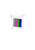
Multifunction DEF Header Unit
Fill Cap
Fill Port Adapter
Tank
1
2
3
4
5
Содержание CLG835H
Страница 2: ......
Страница 4: ...Contents January 24 2017 CLG835H...
Страница 6: ...1 2 General Information January 24 2017 CLG835H...
Страница 38: ...1 34 Machine Inspection Table January 24 2017 CLG835H...
Страница 154: ...2 116 Fault Diagnosis and Troubleshooting January 24 2017 Common fault code and troubleshooting CLG835H...
Страница 156: ...3 2 Power Train System January 24 2017 CLG835H...
Страница 214: ...3 2 Power Train System January 24 2017 CLG835H...
Страница 272: ...3 60 Testing and adjustment January 24 2017 Power Train Test CLG835H...
Страница 276: ...4 4 Hydraulic System January 24 2017 CLG835H...
Страница 296: ...4 24 Structure Function Principle January 24 2017 Work hydraulic system CLG835H Exploded view of control valve P18H00016...
Страница 297: ...4 25 January 24 2017 Structure Function Principle CLG835H Work hydraulic system Exploded view of control valve P18H00017...
Страница 308: ...4 36 Structure Function Principle January 24 2017 Work hydraulic system CLG835H Outline diagram of pilot valve P18H00027...
Страница 506: ...4 234 Fault Diagnosis and Troubleshooting January 24 2017 Common troubleshooting for brake system CLG835H...
Страница 552: ...6 2 Driver s Cab System January 24 2017 CLG835H...
Страница 606: ...6 56 Removal and Installation January 24 2017 Removal and installation of the engine hood torque mechanism CLG835H...
Страница 608: ...7 2 Structure January 24 2017 CLG835H...
Страница 662: ...8 4 Electrical System January 24 2017 CLG835H...
Страница 677: ...8 19 January 24 2017 Structure Function Principle CLG835H Power System P18E00014...
Страница 737: ...8 79 January 24 2017 Structure Function Principle CLG835H Audio system Audio system Audio system principle P18E00138...
Страница 756: ...9 2 Appendix January 24 2017 CLG835H...
Страница 757: ...9 3 January 24 2017 Schematic Diagram of Hydraulic System CLG835H Schematic Diagram of Hydraulic System...
Страница 758: ...9 4 January 24 2017 Schematic Diagram of Brake System CLG835H Schematic Diagram of Brake System...

