7-45
January 24, 2017
Removal and Installation
CLG835H
Removal and installation of work implement system
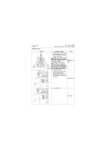
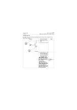
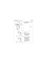
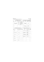
2) Lift the quick coupler frame
to mounting position with
lifting equipment, and align
the lower pin hole with the
front end hole of boom.
WARNNING: Fingers
cannot be put into the
hole when aligning with the
hole, otherwise it may cause
personal injury!
CAUTION: The
personnel operating
lifting equipment shall have
relevant qualifications, and
only can operate on the
premise that equipment and
lifting sling are normal and
safety is guaranteed!
Hoisting equip-
ment (over 3ton)
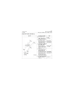
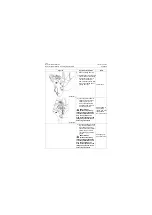
3) Install the bucket lower pins
on left and right sides, and
simultaneously select the
shim with appropriate thick-
ness according to the clear-
ance of quick coupler frame
and boom to make sure the
clearance at one side is
less than 1mm/0.04in.
Sledge hammer
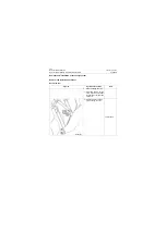
4) Install captive bolts at left
and right sides.
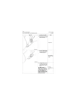
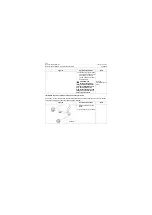
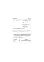
5) Pad the upper pipe of quick
coupler frame with a tooling
with proper height to pre-
vent the quick coupler
frame rotating forward, then
loosen the quick coupler
frame sling.
18# Wrench
Figures
Operation instruction
Tools
P18S00072
P18S00073
Содержание CLG835H
Страница 2: ......
Страница 4: ...Contents January 24 2017 CLG835H...
Страница 6: ...1 2 General Information January 24 2017 CLG835H...
Страница 38: ...1 34 Machine Inspection Table January 24 2017 CLG835H...
Страница 154: ...2 116 Fault Diagnosis and Troubleshooting January 24 2017 Common fault code and troubleshooting CLG835H...
Страница 156: ...3 2 Power Train System January 24 2017 CLG835H...
Страница 214: ...3 2 Power Train System January 24 2017 CLG835H...
Страница 272: ...3 60 Testing and adjustment January 24 2017 Power Train Test CLG835H...
Страница 276: ...4 4 Hydraulic System January 24 2017 CLG835H...
Страница 296: ...4 24 Structure Function Principle January 24 2017 Work hydraulic system CLG835H Exploded view of control valve P18H00016...
Страница 297: ...4 25 January 24 2017 Structure Function Principle CLG835H Work hydraulic system Exploded view of control valve P18H00017...
Страница 308: ...4 36 Structure Function Principle January 24 2017 Work hydraulic system CLG835H Outline diagram of pilot valve P18H00027...
Страница 506: ...4 234 Fault Diagnosis and Troubleshooting January 24 2017 Common troubleshooting for brake system CLG835H...
Страница 552: ...6 2 Driver s Cab System January 24 2017 CLG835H...
Страница 606: ...6 56 Removal and Installation January 24 2017 Removal and installation of the engine hood torque mechanism CLG835H...
Страница 608: ...7 2 Structure January 24 2017 CLG835H...
Страница 662: ...8 4 Electrical System January 24 2017 CLG835H...
Страница 677: ...8 19 January 24 2017 Structure Function Principle CLG835H Power System P18E00014...
Страница 737: ...8 79 January 24 2017 Structure Function Principle CLG835H Audio system Audio system Audio system principle P18E00138...
Страница 756: ...9 2 Appendix January 24 2017 CLG835H...
Страница 757: ...9 3 January 24 2017 Schematic Diagram of Hydraulic System CLG835H Schematic Diagram of Hydraulic System...
Страница 758: ...9 4 January 24 2017 Schematic Diagram of Brake System CLG835H Schematic Diagram of Brake System...

