4-46
Structure Function Principle
January 24, 2017
Brake system
CLG835H
Brake system
A: Overview-components and position
Brake system consists of service brake system,
emergency & parking brake system. Service
brake system is used in speed control and
parking in general traveling. Emergency &
parking brake system is used for brake after
parking, or emergency brake in case of service
brake system failure.
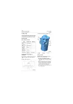
Service brake system consists of brake pump,
brake valve, charge valve, accumulator, wet
brake (in the axle), pressure switch and pipeline.
Emergency & parking brake system consists of
parking brake accumulator, brake cylinder, brake
valve block and pipeline.
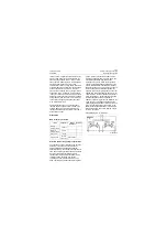
This is a full-hydraulic brake system and its
features are as follows:
1. Using wet-type wheel brake: the system cir-
cuit is fully closed so as to avoid the influence
of external uncertain factors (for example:
sand invasion and oily friction disc) on brak-
ing performance. Using oil-immersed cooling
method by which the friction plate is
immersed in oil to avoid reduction of braking
performance caused by heat fading of friction
material due to high temperature of friction
plate, at the same time, to reduce the
requirement for brake oil.
2. Using full-hydraulic brake system: cancel air
line and simplify the system so as to avoid
the corrosion of pipeline and brake compo-
nents caused by water in the air line system,
and the reliability and response speed of the
system are improved.
3. Using dual-circuit brake: front and rear axle
brake lines are independent so as to make
them safer and more reliable
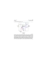
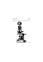
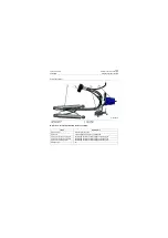
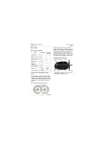
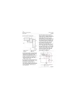
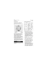
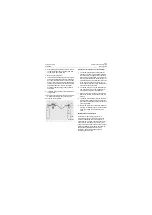
Component layout drawing of full-hydraulic brake
system CLG835H_T4f is as follows: refer to
attached drawing in Chapter 9 for schematic of
braking
Содержание CLG835H
Страница 2: ......
Страница 4: ...Contents January 24 2017 CLG835H...
Страница 6: ...1 2 General Information January 24 2017 CLG835H...
Страница 38: ...1 34 Machine Inspection Table January 24 2017 CLG835H...
Страница 154: ...2 116 Fault Diagnosis and Troubleshooting January 24 2017 Common fault code and troubleshooting CLG835H...
Страница 156: ...3 2 Power Train System January 24 2017 CLG835H...
Страница 214: ...3 2 Power Train System January 24 2017 CLG835H...
Страница 272: ...3 60 Testing and adjustment January 24 2017 Power Train Test CLG835H...
Страница 276: ...4 4 Hydraulic System January 24 2017 CLG835H...
Страница 296: ...4 24 Structure Function Principle January 24 2017 Work hydraulic system CLG835H Exploded view of control valve P18H00016...
Страница 297: ...4 25 January 24 2017 Structure Function Principle CLG835H Work hydraulic system Exploded view of control valve P18H00017...
Страница 308: ...4 36 Structure Function Principle January 24 2017 Work hydraulic system CLG835H Outline diagram of pilot valve P18H00027...
Страница 506: ...4 234 Fault Diagnosis and Troubleshooting January 24 2017 Common troubleshooting for brake system CLG835H...
Страница 552: ...6 2 Driver s Cab System January 24 2017 CLG835H...
Страница 606: ...6 56 Removal and Installation January 24 2017 Removal and installation of the engine hood torque mechanism CLG835H...
Страница 608: ...7 2 Structure January 24 2017 CLG835H...
Страница 662: ...8 4 Electrical System January 24 2017 CLG835H...
Страница 677: ...8 19 January 24 2017 Structure Function Principle CLG835H Power System P18E00014...
Страница 737: ...8 79 January 24 2017 Structure Function Principle CLG835H Audio system Audio system Audio system principle P18E00138...
Страница 756: ...9 2 Appendix January 24 2017 CLG835H...
Страница 757: ...9 3 January 24 2017 Schematic Diagram of Hydraulic System CLG835H Schematic Diagram of Hydraulic System...
Страница 758: ...9 4 January 24 2017 Schematic Diagram of Brake System CLG835H Schematic Diagram of Brake System...


