1-29
January 24, 2017
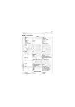
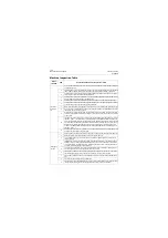
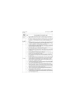
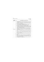
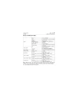
Machine Inspection Table
CLG835H
Climbing up
the cab
10
Horn: press the horn button on the lever of the horn button/control lever on the combination
lever horn button/steering wheel and listen, no abnormal sound and failure to the horn should
occur
Air condition-
ing system
1
The air volume switch, temperature setting switch, defrost setting switch, air mode switch, auto
mode switch on the A/C panel functions normally and is indicated correspondingly on the LCD;
the temperature, air volume, direction at the air outlet is the same with setting value on the
panel.
2
Self-diagnosis of A/C: press the "OFF" switch on the LCD panel, and the temperature setting
and air volume icon on the display disappears; press the up/down regulation button " " and " " on
the temperature setting switch "TEMP" simultaneously for more than 3 seconds. If "E-" appears
on the LCD, it indicates no failure, while "E1" appears, it indicates failures
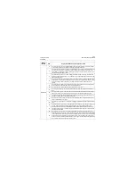
Driving test
1
Starting the complete machine: it starts normally, and listen to the engine and air filter, no abnor-
mal sound is heard, and it turns off normally without delay; observe the engine under the diesel
engine idling and top speed, and it shall not stall
2
Starting the complete machine: adjust the complete machine operating idle speed to a level
more than 950rpm and the engine does not stall with the bucket lifted
3
Starting the complete machine: visual check that no trouble code appears on the LCD of instru-
ment panel, and no indicating identification, alarm and flashing appears on the instrument panel
or normally on.
4
Rearview instrument system (option): when placing the shift lever at reverse, the rearview
instrument activates automatically and the image shall be clear
5
Control lever: there is no seizing and interference with other parts when operating the FNR han-
dle boom to rise, drop, take back and dump the bucket
6
Pilot shutoff function: the pilot shutoff lever is at OFF position, operate the pilot lever and the
work implement shall not act; the pilot shutoff lever is not installed reversely and has no interfer-
ence with housing;
7
Detection of bucket automatic reset: the bucket is unloaded, lift the boom to the highest position
to make the bucket under discharging state and then take back the bucket and it should stop
moving automatically and then control lever returns back to neutral position when the bucket
comes near to the switch and bucket limitation magnet. Then lower the boom to place the
bucket on the ground, at this time, check the bucket and it should be horizontal to the ground;
and the engine is at full throttle during this process
8
Detection of boom automatic reset: boom limitation: lift the boom and it should stop rising when
it reaches the setting highest position; the control lever returns back to neutral position automat-
ically. The engine is at full throttle during this process
9
Work implement limitation: visual check that the bucket limit block contacts with boom and
rocker arm limit block when the boom is lifted to the highest position for discharging; take back
the bucket when the boom descends to a position that its front pin is about 500mm(19.7In) away
from ground, visual check that boom limit block contacts after taking back the bucket and the
clearance between boom and bucket is more than 5mm(0.197In)
10
Inspection of work implement running: lift the boom during which no abnormal sound shall
occur; no twisting to the bucket during taking and holding back the bucket when the boom is
lifted to the highest position and lowest position;
11
Floating function and inner leakage detection: when jacking up the bucket backward, visual
check that the boom does not drop quickly; when the bucket is jacked up, push the control lever
to the boom lowering, floating position, and the control lever shall close, visually check that the
boom shall be floating and lowering
Inspec-
tion item
S/N
Inspection method and acceptance criteria
Содержание CLG835H
Страница 2: ......
Страница 4: ...Contents January 24 2017 CLG835H...
Страница 6: ...1 2 General Information January 24 2017 CLG835H...
Страница 38: ...1 34 Machine Inspection Table January 24 2017 CLG835H...
Страница 154: ...2 116 Fault Diagnosis and Troubleshooting January 24 2017 Common fault code and troubleshooting CLG835H...
Страница 156: ...3 2 Power Train System January 24 2017 CLG835H...
Страница 214: ...3 2 Power Train System January 24 2017 CLG835H...
Страница 272: ...3 60 Testing and adjustment January 24 2017 Power Train Test CLG835H...
Страница 276: ...4 4 Hydraulic System January 24 2017 CLG835H...
Страница 296: ...4 24 Structure Function Principle January 24 2017 Work hydraulic system CLG835H Exploded view of control valve P18H00016...
Страница 297: ...4 25 January 24 2017 Structure Function Principle CLG835H Work hydraulic system Exploded view of control valve P18H00017...
Страница 308: ...4 36 Structure Function Principle January 24 2017 Work hydraulic system CLG835H Outline diagram of pilot valve P18H00027...
Страница 506: ...4 234 Fault Diagnosis and Troubleshooting January 24 2017 Common troubleshooting for brake system CLG835H...
Страница 552: ...6 2 Driver s Cab System January 24 2017 CLG835H...
Страница 606: ...6 56 Removal and Installation January 24 2017 Removal and installation of the engine hood torque mechanism CLG835H...
Страница 608: ...7 2 Structure January 24 2017 CLG835H...
Страница 662: ...8 4 Electrical System January 24 2017 CLG835H...
Страница 677: ...8 19 January 24 2017 Structure Function Principle CLG835H Power System P18E00014...
Страница 737: ...8 79 January 24 2017 Structure Function Principle CLG835H Audio system Audio system Audio system principle P18E00138...
Страница 756: ...9 2 Appendix January 24 2017 CLG835H...
Страница 757: ...9 3 January 24 2017 Schematic Diagram of Hydraulic System CLG835H Schematic Diagram of Hydraulic System...
Страница 758: ...9 4 January 24 2017 Schematic Diagram of Brake System CLG835H Schematic Diagram of Brake System...


