6-10
Removal and Installation
January 24, 2017
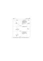
Installation requirements for shock cushion of cab
CLG835H
Removal and Installation
Installation requirements for
shock cushion of cab
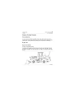
The cushion of cab is installed with M30 bolts
and #46 torque wrench, torque value: tightening
torque (dry state) = 1055 N·m.
Removal and installation of cab
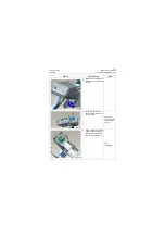
Disassembly order of cab lifting
1. Remove A/C components
→
remove hydrau-
lic components
→
remove power compo-
nents
→
remove electrical components
→
replace lifting rings of head cover
→
remove
cushion
→
lift.
2. Step of installing cab onto machine: install it
by the opposite steps of removal.
Removal of air conditioning
components in cab
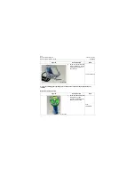
Disassembly of air conditioning connector
Fluoridation of air conditioning
For fluoridation of air conditioning, refer to the
section of air conditioning in this manual.
Disassembly of hydraulic components
in cab
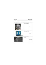
Remove brake pedal
1. Removal steps of brake valve from the
machine:
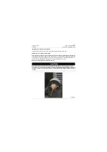
Before removing brake valve, make sure that
the machine is in parking brake state.
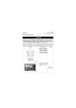
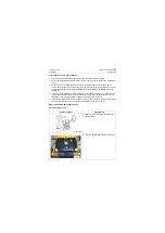
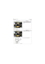
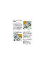
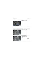
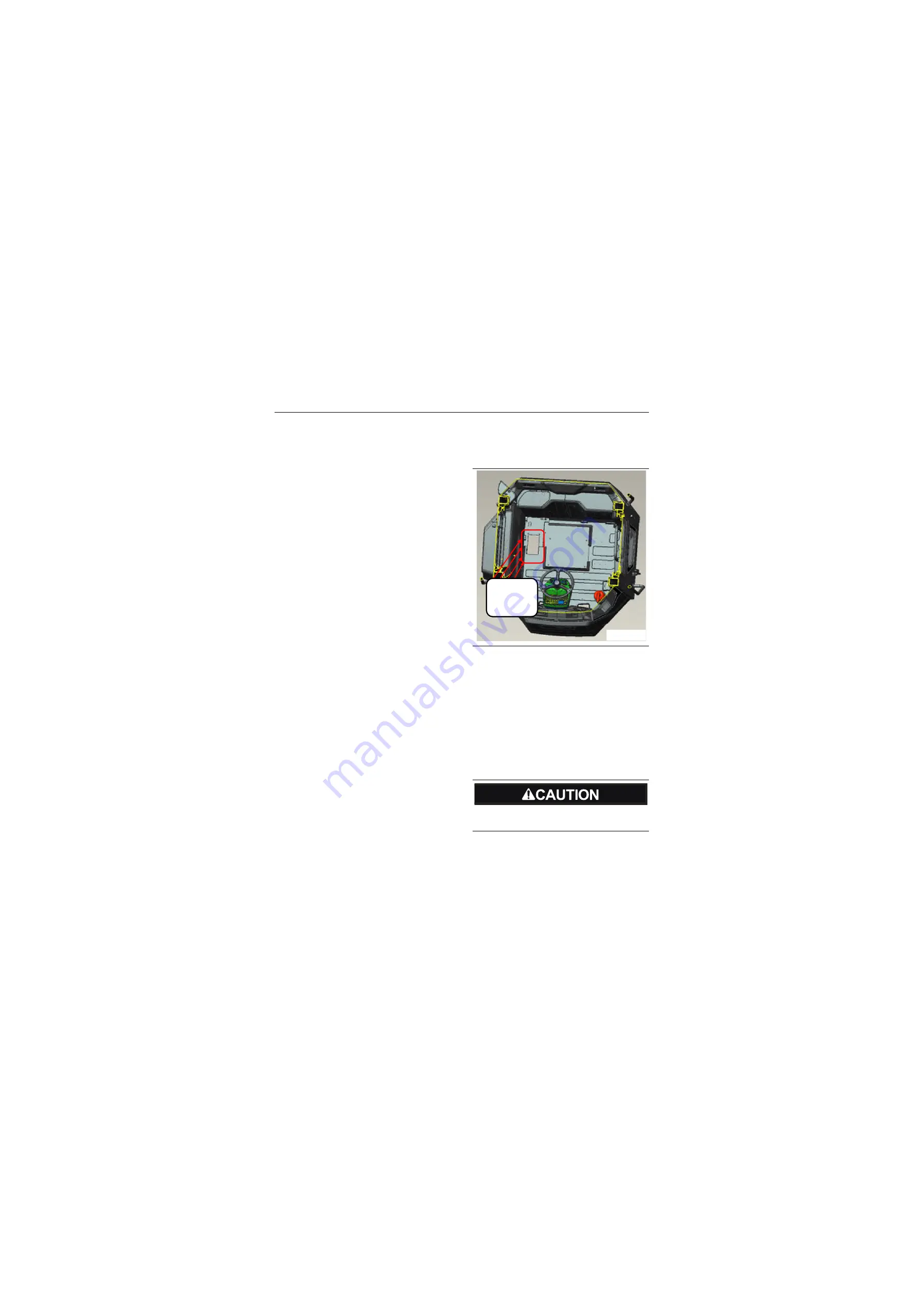
When removing
the driver cab,
these four A/C
poles shall be
removed
P18C00014
Содержание CLG835H
Страница 2: ......
Страница 4: ...Contents January 24 2017 CLG835H...
Страница 6: ...1 2 General Information January 24 2017 CLG835H...
Страница 38: ...1 34 Machine Inspection Table January 24 2017 CLG835H...
Страница 154: ...2 116 Fault Diagnosis and Troubleshooting January 24 2017 Common fault code and troubleshooting CLG835H...
Страница 156: ...3 2 Power Train System January 24 2017 CLG835H...
Страница 214: ...3 2 Power Train System January 24 2017 CLG835H...
Страница 272: ...3 60 Testing and adjustment January 24 2017 Power Train Test CLG835H...
Страница 276: ...4 4 Hydraulic System January 24 2017 CLG835H...
Страница 296: ...4 24 Structure Function Principle January 24 2017 Work hydraulic system CLG835H Exploded view of control valve P18H00016...
Страница 297: ...4 25 January 24 2017 Structure Function Principle CLG835H Work hydraulic system Exploded view of control valve P18H00017...
Страница 308: ...4 36 Structure Function Principle January 24 2017 Work hydraulic system CLG835H Outline diagram of pilot valve P18H00027...
Страница 506: ...4 234 Fault Diagnosis and Troubleshooting January 24 2017 Common troubleshooting for brake system CLG835H...
Страница 552: ...6 2 Driver s Cab System January 24 2017 CLG835H...
Страница 606: ...6 56 Removal and Installation January 24 2017 Removal and installation of the engine hood torque mechanism CLG835H...
Страница 608: ...7 2 Structure January 24 2017 CLG835H...
Страница 662: ...8 4 Electrical System January 24 2017 CLG835H...
Страница 677: ...8 19 January 24 2017 Structure Function Principle CLG835H Power System P18E00014...
Страница 737: ...8 79 January 24 2017 Structure Function Principle CLG835H Audio system Audio system Audio system principle P18E00138...
Страница 756: ...9 2 Appendix January 24 2017 CLG835H...
Страница 757: ...9 3 January 24 2017 Schematic Diagram of Hydraulic System CLG835H Schematic Diagram of Hydraulic System...
Страница 758: ...9 4 January 24 2017 Schematic Diagram of Brake System CLG835H Schematic Diagram of Brake System...

