7-33
January 24, 2017
Removal and Installation
CLG835H
Removal and installation of work implement system
Replacement of boom shaft bushing
Figures
Operation instruction
Tools
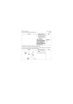
Replace the boom bushing
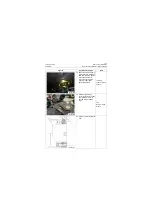
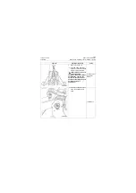
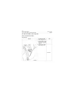
1. Remove seal rings (3, 6)
with a straight screwdriver
Straight
screwdriver
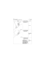
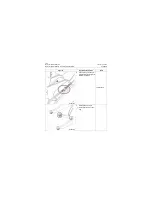
2. Knock frame bushing (2),
boom bushing (4) and
bushing (5) out in sequence
with bushing knocking
tooling and sledge hammer.
Shaft bushing
knocking tooling,
sledge hammer
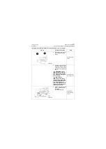
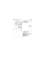
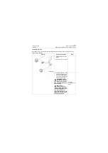
3. Put new frame bushing (2),
boom bushing (4) and
bushing (5) into liquid
nitrogen for freezing until
there is not a lot of smoke
coming out.
Liquid nitrogen,
hook fixture
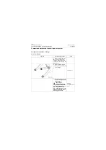
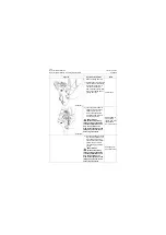
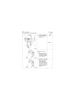
4. Install frozen frame shaft
bushing (2), boom shaft
bushing (4) and shaft
bushing (5) into the boom
(1) in sequence with shaft
bushing knocking tooling
and sledge hammer, and
reserve mounting position
for seal rings on both sides.
Shaft bushing
knocking tooling,
sledge hammer
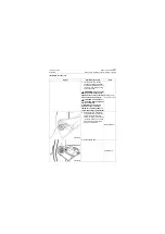
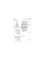
5. Knock seal rings (3, 6) into
the boom (1) gently with
copper bar
Copper bar
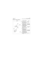
P18S00053
1. Boom
2. Frame bushing
3. Boom bushing
4. Bushing
5. Seal ring
Содержание CLG835H
Страница 2: ......
Страница 4: ...Contents January 24 2017 CLG835H...
Страница 6: ...1 2 General Information January 24 2017 CLG835H...
Страница 38: ...1 34 Machine Inspection Table January 24 2017 CLG835H...
Страница 154: ...2 116 Fault Diagnosis and Troubleshooting January 24 2017 Common fault code and troubleshooting CLG835H...
Страница 156: ...3 2 Power Train System January 24 2017 CLG835H...
Страница 214: ...3 2 Power Train System January 24 2017 CLG835H...
Страница 272: ...3 60 Testing and adjustment January 24 2017 Power Train Test CLG835H...
Страница 276: ...4 4 Hydraulic System January 24 2017 CLG835H...
Страница 296: ...4 24 Structure Function Principle January 24 2017 Work hydraulic system CLG835H Exploded view of control valve P18H00016...
Страница 297: ...4 25 January 24 2017 Structure Function Principle CLG835H Work hydraulic system Exploded view of control valve P18H00017...
Страница 308: ...4 36 Structure Function Principle January 24 2017 Work hydraulic system CLG835H Outline diagram of pilot valve P18H00027...
Страница 506: ...4 234 Fault Diagnosis and Troubleshooting January 24 2017 Common troubleshooting for brake system CLG835H...
Страница 552: ...6 2 Driver s Cab System January 24 2017 CLG835H...
Страница 606: ...6 56 Removal and Installation January 24 2017 Removal and installation of the engine hood torque mechanism CLG835H...
Страница 608: ...7 2 Structure January 24 2017 CLG835H...
Страница 662: ...8 4 Electrical System January 24 2017 CLG835H...
Страница 677: ...8 19 January 24 2017 Structure Function Principle CLG835H Power System P18E00014...
Страница 737: ...8 79 January 24 2017 Structure Function Principle CLG835H Audio system Audio system Audio system principle P18E00138...
Страница 756: ...9 2 Appendix January 24 2017 CLG835H...
Страница 757: ...9 3 January 24 2017 Schematic Diagram of Hydraulic System CLG835H Schematic Diagram of Hydraulic System...
Страница 758: ...9 4 January 24 2017 Schematic Diagram of Brake System CLG835H Schematic Diagram of Brake System...

