8-32
Structure Function Principle
January 24, 2017
Monitoring system
CLG835H
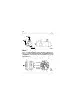
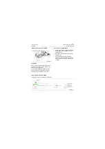
Fuel level sensor
Floaters are applied in the sensor, which shift up
and down along with the oil level of the fuel tank.
The floater influences the resistance value pass-
ing through the sensor. Once the circuit is con-
nected, the characteristics of resistance
changing with oil level are converted to that of
voltage varying with oil level. The changing volt-
age signal enters into the microcontroller of com-
bination instrument, which outputs signal through
the operation processing of microcontroller, to
drive the stepping motor-type instrument for oil
level indication.
Precautions
Switch off the electric lock, and replace the fuel
level sensor until the machine is completely
cooled if necessary. When replacing, prevent for-
eign matters from getting into the diesel tank.
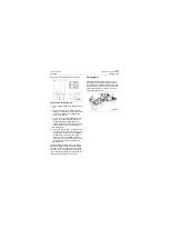
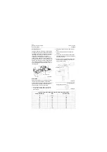
Test steps of fuel oil level sensor faults
1. Disconnect the wiring harness of fuel level
sensor and the wiring harness of the com-
plete vehicle;
2. Remove the fuel level sensor from the fuel
tank;
3. Turn the digital multimeter to 10
00
Ω
of
Ω
position.
4. Connect the red probe to the terminal at #1
hole site of the sensor connector, while black
probe to #2 hole site;
5. Measure the varied resistance values of fuel
level sensor corresponding to the different
positions of the floater;
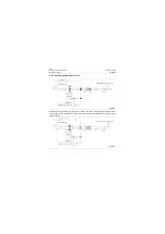
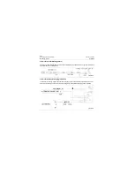
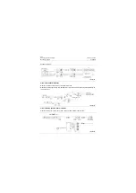
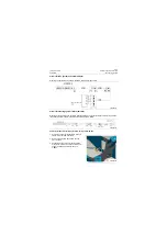
Fuel level sensor
P18E00032
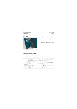
P18E00033
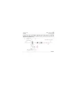
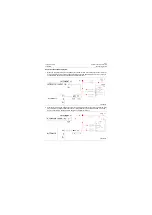
Sealing washer
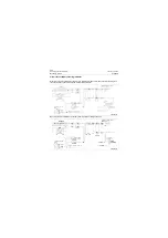
Oil level
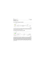
P18E00034
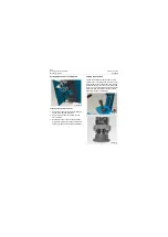
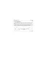
Sensor signal terminal (green)
Earthing cable (black)
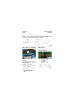
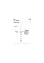
Technical parameters (After floater rises to the top, then drop to test)
Floater position (H)
Gear
Resistance (
Ω
)
<65
Full level
68
65
8/9
136
94
7/9
204
123
6/9
272
152
5/9
340
181
4/9
408
210
3/9
476
242
2/9
544
277
1/9
612
316
0 level
680
Содержание CLG835H
Страница 2: ......
Страница 4: ...Contents January 24 2017 CLG835H...
Страница 6: ...1 2 General Information January 24 2017 CLG835H...
Страница 38: ...1 34 Machine Inspection Table January 24 2017 CLG835H...
Страница 154: ...2 116 Fault Diagnosis and Troubleshooting January 24 2017 Common fault code and troubleshooting CLG835H...
Страница 156: ...3 2 Power Train System January 24 2017 CLG835H...
Страница 214: ...3 2 Power Train System January 24 2017 CLG835H...
Страница 272: ...3 60 Testing and adjustment January 24 2017 Power Train Test CLG835H...
Страница 276: ...4 4 Hydraulic System January 24 2017 CLG835H...
Страница 296: ...4 24 Structure Function Principle January 24 2017 Work hydraulic system CLG835H Exploded view of control valve P18H00016...
Страница 297: ...4 25 January 24 2017 Structure Function Principle CLG835H Work hydraulic system Exploded view of control valve P18H00017...
Страница 308: ...4 36 Structure Function Principle January 24 2017 Work hydraulic system CLG835H Outline diagram of pilot valve P18H00027...
Страница 506: ...4 234 Fault Diagnosis and Troubleshooting January 24 2017 Common troubleshooting for brake system CLG835H...
Страница 552: ...6 2 Driver s Cab System January 24 2017 CLG835H...
Страница 606: ...6 56 Removal and Installation January 24 2017 Removal and installation of the engine hood torque mechanism CLG835H...
Страница 608: ...7 2 Structure January 24 2017 CLG835H...
Страница 662: ...8 4 Electrical System January 24 2017 CLG835H...
Страница 677: ...8 19 January 24 2017 Structure Function Principle CLG835H Power System P18E00014...
Страница 737: ...8 79 January 24 2017 Structure Function Principle CLG835H Audio system Audio system Audio system principle P18E00138...
Страница 756: ...9 2 Appendix January 24 2017 CLG835H...
Страница 757: ...9 3 January 24 2017 Schematic Diagram of Hydraulic System CLG835H Schematic Diagram of Hydraulic System...
Страница 758: ...9 4 January 24 2017 Schematic Diagram of Brake System CLG835H Schematic Diagram of Brake System...


