diamond - User Manual
Version: 8.0.0/1
Exported on: 24 October, 2023
52
/
228
•
•
•
•
4. Configure the surface modules.
This step ensures that the IP module knows about all other modules in the frame, and that the correct slot IDs are
assigned.
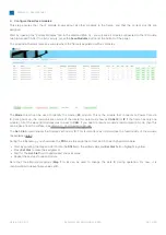
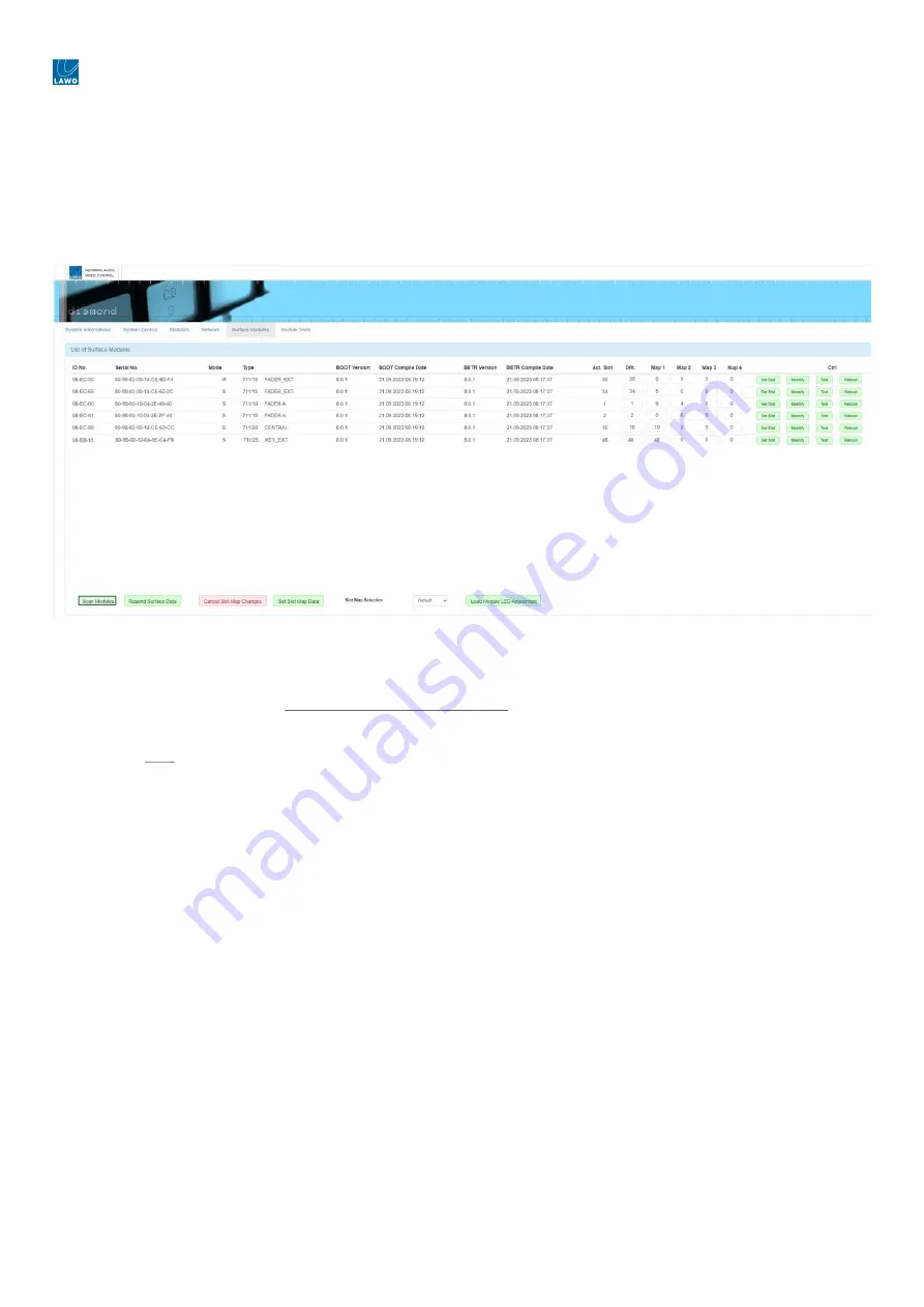
Start by opening the "Surface Modules" tab in the diamond Web UI - you will see all modules connected to the IP module
(via high-speed CAN). If the list is empty, press the
Scan Modules
button (at the bottom of the page).
The screenshot below shows an example where the frame is populated with six modules.
The
Mode
column can be used to identify the master (
M
) module. This is the module that connects to Power Core via
IP. During
boot-up, the communication mode of the master module must show as
CAN+IP
(or
IP
if the frame has only one
module). All of the slave (
S
) modules must be set to
CAN
. If you need to reset a module's communication mode, then this
can be done from the surface. See diamond - Communication Modes.
The
Act. Slot
column shows
the module's active slot ID. This is important as it determines the functionality of the module
(as explained later).
During the initial setup, you should use
the
Dflt
value to assign the correct slot ID to each physical module.
Start by entering the required slot ID into
the
Dflt
field - the edited value
and
Set Slot
button
highlight in yellow.
Press
Set Slot
to
make the assignment.
Wait for
the
Act. Slot
field
to update and check its value.
Repeat these steps for each module.
Note that the alternate mappings (
Map 1
to
4
) can be used to change the slots ID during operation. For now, it is
recommended to leave these values at
0
.


