Handbook OPTIFLEX 1300 C
77 OPTIFLEX
1300
C
5.
Functional checks
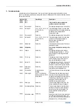
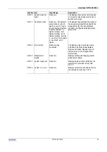
Using the device menu Program mode > Test, you can check the device outputs and perform common
tests. You can display output values or assign test values in milliamperes to the outputs. In addition, internal
test routines can be run.
Function (Fct.)
Input Range
Description
B.0.0.0 Test
B.1.0.0 Test
This checks the device outputs and
performs common device tests.
B.1.1.0 Show output 1
Read only.
This displays analogue output 1 value [mA].
B.1.2.0 Set output 1
3.6, 4, 6, 8, 10, 12, 14, 16,
18, 20 or 22 mA.
4 mA
This sets analogue output 1 to a test value
[mA] selected from a list. Output will change
to selected value, independent of
measurement value.
B.1.3.0 Show output 2
Read only.
This displays analogue output 2 value [mA].
B.1.4.0 Set output 2
3.6, 4, 6, 8, 10, 12, 14, 16,
18, 20 or 22 mA.
4 mA
This sets analogue output 2 to a test value
[mA] from a list. Output will change to
selected value, independent of
measurement value.
B.1.5.0 Internal test
Read only.
This initiates the hardware test. The device
displays the results.
B.2.0.0 Information
A summary of information relating to the
device.
B.2.1.0 Outputs
Read only.
This displays analogue output settings
including assigned functions, 4 … 20 mA
scale settings, error handling and HART
parameters.
B.2.2.0 15 min. log
Read only.
This displays a log of output values for the
last 15 minutes. A log is taken every 10
seconds and displayed as a graph.
B.2.3.0 Device I.D.
Read only.
This displays device order no, V-no, service
no, firmware 1 version, firmware 2 version,
firmware 3 version and Ex approval details.
B.2.4.0 Quick setup
summary
Read only.
Summary of the parameters entered in the
Quick setup menu is displayed here.
B.2.5.0 TAG number
9 characters max.
Krohne
The TAG number can be seen and updated
here
B.2.6.0 Probe length
From C.1.9.0 Blocking
distance to 60 m or 197 ft.
3 m or 10 ft
The distance from the flange face/thread
stop down to the bottom end of the probe
(including counterweight for cable versions).
The factory set value for probe length is
displayed. If probe length has been
modified, the new value is shown.
B.2.7.0 Probe type
Read only.
The mechanical design of the probe. The
factory installed probe type is displayed.
B.2.8.0 Counterweight type Read only.
The mechanical design of a cable probe's
bottom end. The device will not measure
below the top of the counterweight. The
factory-installed counterweight type is
displayed.
B.2.9.0 Calculated
ε
r
value
Read only.
Dielectric constant [
ε
r
] is a major parameter
for TDR level measurement devices. This
device is able to automatically calculate and
display here the
ε
r
of the top product.
Содержание optiplex 1300 c
Страница 1: ......
Страница 49: ...Handbook OPTIFLEX 1300 C 49 OPTIFLEX 1300 C 1 Volume measurement of liquids...
Страница 50: ...Handbook OPTIFLEX 1300 C OPTIFLEX 1300 C 50 2 Volume measurement of solids...
Страница 51: ...Handbook OPTIFLEX 1300 C 51 OPTIFLEX 1300 C 3 Mass measurement of liquids or solids...
Страница 62: ...Handbook OPTIFLEX 1300 C OPTIFLEX 1300 C 62 Finding the advanced setup menu...
Страница 95: ...Handbook OPTIFLEX 1300 C 95 OPTIFLEX 1300 C Note...

