Handbook OPTIFLEX 1300 C
69 OPTIFLEX
1300
C
Measuring mode
function C.1.13.0
The supervisor can use this function to measure products with low dielectric constants (
ε
r
≤
1.6). For further
information regarding the measuring modes, please refer to the section 8: Measuring principle.
Three modes are available:
•
Automatic: the device selects either direct or TBF measurement mode based on parameters set in
program mode and the strength of the reflection from the product
•
Direct: measurement is made from the reflection received directly from the product surface
•
TBF: TBF is an indirect measurement mode used measuring level of low-dielectric products only. Most
of the signal goes through the product and reflects off the end of the probe. In order for the device to
measure precisely and reliably, the product has to have a stable and constant dielectric constant. The
function Product
ε
r
C.1.15.0 should also be used for these applications.
Product
ε
r
function C.1.14.0 [only when using TBF mode or measuring interface]
An exact value for dielectric constant,
ε
r
, should be entered when measuring products with low dielectric
constant. If this value is not known, then leave at the default value of 2. However, in this case expect
reduced accuracy and/or skipping of the measured value on changeover from TBF to direct mode. If too low
then the level will read higher than it actually is and vice versa.
Gas
ε
r
function C.1.15.0
In solid applications where there is a lot of dust in the air above the product it may be necessary increase
the value of Gas
ε
r
slightly to improve accuracy. Also use this function if the probe is completely coated with
a regular layer of residue or dust from the product.
For all other applications use the default value of 1.
Please contact our local service centre for further assistance.
Thresholds
Description
As explained in the measuring principle, OPTIFLEX 1300 C emits a low-power electromagnetic signal that
reflects back from the product surface and any other objects within its field. These signals are converted to
voltage amplitudes by the signal converter.
Reflections from the internal tank components represent parasite or interference signals. Thresholds permit
the device to ignore small amplitude reflections and follow changes in product level correctly. As voltage
amplitude also decreases over distance, this threshold decreases according to a mathematical formula. The
first return signal over the threshold is identified as the product surface. Once identified, the signal converter
has to process the signal: it amplifies the signal (defined by levels of Gain: 0 to 7) to use it for measurement
purposes. A strong return signal will be given a Gain 0 or no amplification, while a weak signal will be given
Gain 7 or high amplification.
Normally the signal converter will automatically identify the signals to be measured and adjust the Gain to
follow the same signal along the length of the probe as the tank is filled or emptied. However, if there are
large and/or too many other objects in the tank and the signal converter has problems following the signal
then you can adjust the threshold manually to suit the installation.
Содержание optiplex 1300 c
Страница 1: ......
Страница 49: ...Handbook OPTIFLEX 1300 C 49 OPTIFLEX 1300 C 1 Volume measurement of liquids...
Страница 50: ...Handbook OPTIFLEX 1300 C OPTIFLEX 1300 C 50 2 Volume measurement of solids...
Страница 51: ...Handbook OPTIFLEX 1300 C 51 OPTIFLEX 1300 C 3 Mass measurement of liquids or solids...
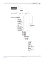
Страница 62: ...Handbook OPTIFLEX 1300 C OPTIFLEX 1300 C 62 Finding the advanced setup menu...
Страница 95: ...Handbook OPTIFLEX 1300 C 95 OPTIFLEX 1300 C Note...


