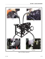
SECTION 3 - CHASSIS & TURNTABLE
3-162
3121160
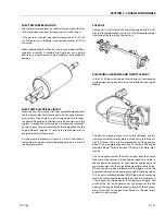
Lockoff Solenoid
The lockoff solenoid is used to reduce the possibility of back-
fires. The EPM controls the opening and closing of the lockoff
so that as a shutdown is commanded, the lockoff is closed, but
the ignition system continues to operate to burn off unburned
fuel in the manifold. This will cause longer than usual start
times, because the manifold must fill up with fuel again before
the engine will fire. This will also cause the engine to run for
one to two seconds after ignition is turned off.
Megajector Diagnostic Code Descriptions
The following diagnostic codes are specific to the megajector.
They will be displayed on the analyzer if the JLG Control Sys-
tem senses a fault dealing with the megajector. Refer to Sec-
tion 6 - JLG Control System for more information concerning
the Control System.
DTC 353
- Megajector delivery pressure higher than expected.
This code will set if the difference between the Megajector
actual pressure and the Megajector commanded pressure is
greater than 4.00 in. (10.1 cm) of H
2
O.
a. Fuel Supply
- Check fuel supply pressure at the
megajector inlet fitting. Fuel supply pressure on LPG
applications should be between 3-5 in. (7.6-12.7 cm)
H
2
O.
b. Lockoff Solenoid
- Check the lockoff to make sure it
is sealing when closed. If it is not completely sealing,
it could allow pressure creep in the fuel system.
c. Reference Line
- Make sure the reference line is in
place between the Megajector and the carburetor
balance port. Make sure the hose is not kinked or
restricted in any way and has no holes in it.
d. Regulator
- Observe the regulator with the engine
running to see if it is icing up. If it’s icing up, refer to
Engine Cooling System below.
e. Engine Cooling System
- Make sure the engine
cooling system is operating properly and there are
no air locks in the system. Make sure the engine is
operating at the proper temperature. Check the
coolant hoses at the regulator and make sure they
are both warm to verify proper coolant circulation.
If the fuel system is operating properly, the Megajector has an
internal failure and must be replaced.
DTC 354
- Megajector delivery pressure lower than expected.
This code will set if the difference between the Megajector
actual pressure and the Megajector commanded pressure is
less than -4.00 in. (10.1 cm) of H
2
O.
a. Fuel Supply
- Check fuel supply pressure at the
megajector inlet fitting. Fuel supply pressure on LPG
applications should be between 3-5 in. (7.6-12.7 cm)
H
2
O.
b. Fuel System Hoses
- Make sure all fuel system
hoses are in good condition. They should be
clamped tight, free from kinks with no cuts, pinches,
etc.
c. Lockoff Solenoid
- Check the lock off to make sure
it is opening properly. If it is not opening com-
pletely, it could cause low fuel pressure.
d. Reference Line
- Make sure the reference line is in
place between the Megajector and the carburetor
balance port. Make sure the hose is not kinked or
restricted in any way and has no holes in it.
e. Regulator
- Observe the regulator with the engine
running to see if it is icing up. If it’s icing up, refer to
Engine Cooling System below.
f. Engine Cooling System
- Make sure the engine
cooling system is operating properly and there are
no air locks in the system. Make sure the engine is
operating at the proper temperature. Check the
coolant hoses at the regulator and make sure they
are both warm to verify proper coolant circulation.
If the fuel system is operating properly, the Megajector has an
internal failure and must be replaced.
DTC 355
- Megajector comm. lost. This codes will set if the
communication (CAN link) between the Megajector and the
EPM is not present.
a. CAN Circuits
- Check CAN circuits for continuity and
shorts to power or ground and for proper connec-
tions.
If the CAN circuits are ok and all wiring connections are good,
the Megajector has an internal failure and must be replaced.
DTC 361
- Megajector voltage supply high.
a. Voltage
- Check battery voltage. If the voltage at
the battery is greater than 18 volts, either the charg-
ing system or the megajector is faulty.
Содержание 740AJ
Страница 1: ...Service and Maintenance Manual Model 740AJ Prior to S N 0300185827 P N 3121160 October 24 2017 AS NZS...
Страница 2: ......
Страница 51: ...SECTION 2 GENERAL 3121160 2 11 Figure 2 2 Engine Operating Temperature Specifications Ford 4150548 E...
Страница 55: ...SECTION 3 CHASSIS TURNTABLE 3121160 3 3 This page left blank intentionally...
Страница 56: ...SECTION 3 CHASSIS TURNTABLE 3 4 3121160 1 Figure 3 2 Axle and Steering Installation Sheet 1 of 2 0258286 C...
Страница 100: ...SECTION 3 CHASSIS TURNTABLE 3 48 3121160 Figure 3 37 Swing Bearing Tolerance Boom Placement Sheet 1 of 2...
Страница 101: ...SECTION 3 CHASSIS TURNTABLE 3121160 3 49 Figure 3 38 Swing Bearing Tolerance Boom Placement Sheet 2 of 2...
Страница 116: ...SECTION 3 CHASSIS TURNTABLE 3 64 3121160 Figure 3 44 Swing Hub Prior to SN 0300074383...
Страница 124: ...SECTION 3 CHASSIS TURNTABLE 3 72 3121160 Figure 3 45 Swing Drive Hub Fairfield SN 0300074383 through 0300134352...
Страница 180: ...SECTION 3 CHASSIS TURNTABLE 3 128 3121160 1 Figure 3 66 Auxiliary Pump Location 1 AuxiliaryPump 2 HydraulicTank...
Страница 203: ...SECTION 3 CHASSIS TURNTABLE 3121160 3 151 Figure 3 77 EFI Component Location...
Страница 206: ...SECTION 3 CHASSIS TURNTABLE 3 154 3121160 Figure 3 78 ECM EPM Identification ECM EPM...
Страница 213: ...SECTION 3 CHASSIS TURNTABLE 3121160 3 161 Megajector Regulator LockoffSolenoid Figure 3 80 LPG System Components Mixer...
Страница 219: ...SECTION 3 CHASSIS TURNTABLE 3121160 3 167 Figure 3 81 Check Out and Initial Start Up Procedures...
Страница 224: ...SECTION 3 CHASSIS TURNTABLE 3 172 3121160 Figure 3 83 Deutz EMR 2 Troubleshooting Flow Chart...
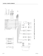
Страница 225: ...SECTION 3 CHASSIS TURNTABLE 3121160 3 173 Figure 3 84 Deutz EMR 2 Vehicle Side Connection Diagram...
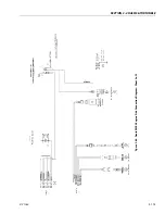
Страница 226: ...SECTION 3 CHASSIS TURNTABLE 3 174 3121160 Figure 3 85 Deutz EMR 2 Engine Side Connection Diagram Sheet 1 of 2...
Страница 227: ...SECTION 3 CHASSIS TURNTABLE 3121160 3 175 Figure 3 86 Deutz EMR 2 Engine Side Connection Diagram Sheet 2 of 2...
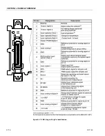
Страница 228: ...SECTION 3 CHASSIS TURNTABLE 3 176 3121160 Figure 3 87 EMR 2 Engine Plug Pin Identification...
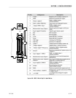
Страница 229: ...SECTION 3 CHASSIS TURNTABLE 3121160 3 177 Figure 3 88 EMR 2 Vehicle Plug Pin Identification...
Страница 230: ...SECTION 3 CHASSIS TURNTABLE 3 178 3121160 Figure 3 89 EMR2 Fault Codes Sheet 1 of 5...
Страница 231: ...SECTION 3 CHASSIS TURNTABLE 3121160 3 179 Figure 3 90 EMR2 Fault Codes Sheet 2 of 5...
Страница 232: ...SECTION 3 CHASSIS TURNTABLE 3 180 3121160 Figure 3 91 EMR2 Fault Codes Sheet 3 of 5...
Страница 233: ...SECTION 3 CHASSIS TURNTABLE 3121160 3 181 Figure 3 92 EMR2 Fault Codes Sheet 4 of 5...
Страница 234: ...SECTION 3 CHASSIS TURNTABLE 3 182 3121160 Figure 3 93 EMR2 Fault Codes Sheet 5 of 5...
Страница 303: ...SECTION 4 BOOM PLATFORM 3121160 4 31 Figure 4 20 Rotator Assembly HELAC...
Страница 335: ...SECTION 4 BOOM PLATFORM 3121160 4 63 THIS SENSOR ON NON ADE MACHINES ONLY Figure 4 27 UMS Sensor Location...
Страница 336: ...SECTION 4 BOOM PLATFORM 4 64 3121160 Figure 4 28 UMS Module Location ADE MACHINES NON ADE MACHINES...
Страница 425: ...SECTION 5 BASIC HYDRAULIC INFORMATION AND SCHEMATICS 3121160 5 81 Figure 5 131 Variable Displacement Pump Rexroth...
Страница 443: ...SECTION 5 BASIC HYDRAULIC INFORMATION AND SCHEMATICS 3121160 5 99 Figure 5 146 Fault Logic Troubleshooting...
Страница 444: ...SECTION 5 BASIC HYDRAULIC INFORMATION AND SCHEMATICS 5 100 3121160 Figure 5 147 Fault Logic Troubleshooting...
Страница 445: ...SECTION 5 BASIC HYDRAULIC INFORMATION AND SCHEMATICS 3121160 5 101 Figure 5 148 Fault Logic Troubleshooting...
Страница 460: ...SECTION 5 BASIC HYDRAULIC INFORMATION AND SCHEMATICS 5 116 3121160 NOTES...
Страница 467: ...SECTION 6 JLG CONTROL SYSTEM 3121160 6 7 Figure 6 2 ADE Block Diagram...
Страница 471: ...SECTION 6 JLG CONTROL SYSTEM 3121160 6 11 Figure 6 6 Analyzer Flow Chart Prior to Version 5 X Software Sheet 4 of 4...
Страница 473: ...SECTION 6 JLG CONTROL SYSTEM 3121160 6 13 Figure 6 8 Analyzer Flow Chart Version 5 X Software Sheet 2 of 4...
Страница 534: ...SECTION 6 JLG CONTROL SYSTEM 6 74 3121160 NOTES...
Страница 545: ...SECTION 7 BASIC ELECTRICAL INFORMATION SCHEMATICS 3121160 7 11 Figure 7 15 Connector Installation...
Страница 580: ...SECTION 7 BASIC ELECTRICAL INFORMATION SCHEMATICS 7 46 3121160 NOTES...
Страница 581: ......

