


SECTION 3 - CHASSIS & TURNTABLE
3-96
3121160
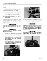
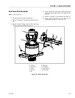
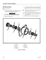
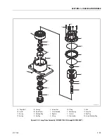
Hub-Shaft Assembly
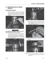
NOTE:
Refer to Figure 3-51.
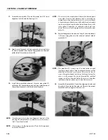
1.
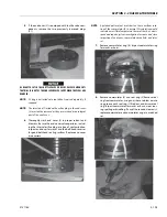
Press Bearing Cup (1C) into Housing (1G) taking care to
insure cup starts square with the bore of Hub (1G).
2.
Place Bearing Cone (1D) in Bearing Cup (1C) in Housing
(1G).
3.
Press or tap Seal (1B) Into the counterbore of Housing
(1G) to the point where it becomes flush with the Hous-
ing (1G) face. Care should be taken to insure Seal (1B) is
being correctly installed (smooth face up). Apply grease
to the rubber portion of the seal bore.
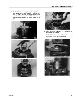
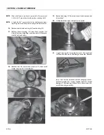
4.
Invert Hub (1G) and press Bearing Cup (1E) into counter-
bore of Housing (1G).
5.
Carefully lower Housing (1G) onto the Output Shaft (1A)
until Bearing Cone (1D) contacts the Output Shaft (1A).
6.
Press on the small end of the Bearing Cone (1D), being
careful not to contact the bearing cage, until the Bearing
Cone (1D) seats on the shoulder of the Output Shaft
(1A).
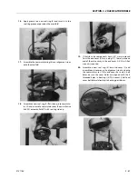
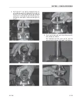
7.
Start the Bearing Cone (1F) onto the Output Shaft (1A).
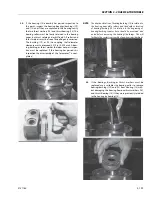
8.
Press or tap the Bearing Cone (1F) onto the Output Shaft
(1A) until it is just seated in the Bearing Cup (1E) while
rotating the Housing (G).
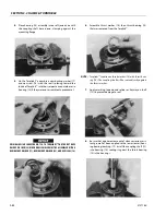
9.
Install Bearing Spacer (1H) onto Output Shaft (1A) and
against Bearing Cone (1F).
10.
Install Retaining Ring (1I) into the groove in the Output
Shaft (1A). This Retaining Ring (1I) should never be
reused in a repair or rebuild.
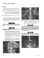
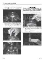
EYE PROTECTION SHOULD BE WORN DURING THIS PROCEDURE.
11.
Tap the Retaining Ring (1I) with a soft metal punch to
ensure that the Retaining Ring (1I) is completely seated
in the groove of the Output Shaft (IA).
EYE PROTECTION SHOULD BE WORN DURING THIS PROCEDURE.
12.
Install O-ring Plug (1P) and torque to 23 to 24 ft. lbs.
(31 to 32 Nm).
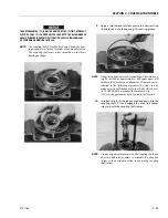
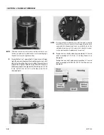
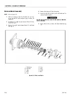
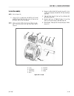
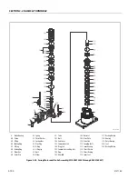
Carrier Assembly
NOTE:
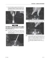
1.
Apply a liberal Coat of grease to the bore of Cluster Gear
(3F). This will enable the Needle Rollers (3C) to be held in
place during assembly.
2.
Install the first row of Needle Rollers (3C) into the bore of
Cluster Gear (3F).
3.
Insert Spacer (3D) into bore of Cluster Gear (3F) on top of
the Needle Rollers (3C).
4.
Place second row of Needle Rollers (3C) into bore of
Cluster Gear (3F) against Spacer (3D).
5.
Place Carrier (3A) so that one of the roll pin holes is
straight up.
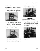
6.
Start Planet Shaft (3E) through the hole in Carrier (3A).
Using ample grease to hold it in position, slide one
Thrust Washer (3B) over the Planet Shaft (3E) with the
tang resting in the cast slot of the Carrier (3A).
7.
With large end of Cluster Gear (3F) facing the roll pin
hole in the Carrier, place the Cluster Gear into position in
carrier (3A) and push Planet Shaft (3E) through the Clus-
ter Gear (3F) without going all the way through.
8.
Slide the second Thrust Washer (3B) between the Cluster
Gear (3F) and the Carrier (3A) with the tang of the
washer located in the cast slot of the Carrier (3A). Finish
sliding the Planet Shaft (3E) through the Thrust Washer
(3B) and into the Carrier (3A).
9.
Position the non-chamfered side on the Planet Shaft (3E)
roll pin hole so that it is in line with the hole in the Car-
rier (3A) using a 1/8 in. (3 mm) diameter punch.
10.
After using a 3/16 in. (5 mm) punch to align the two roll
pin holes. Drive the Roll Pin (3G) through Carrier (3A)
and into the Planet Shaft (3E) until the Roll Pin (3G) is
flush with the bottom of the cast slot in the Carrier (3A)
outside diameter at the thrust washer (3B) tang. Use a 1/
4 in. (6 mm) pin punch to make sure the Roll Pin (3G) is
flush in the slot.
11.
Repeat Steps 1 through 10 for the remaining two Cluster
Gears (3F).
Содержание 740AJ
Страница 1: ...Service and Maintenance Manual Model 740AJ Prior to S N 0300185827 P N 3121160 October 24 2017 AS NZS...
Страница 2: ......
Страница 51: ...SECTION 2 GENERAL 3121160 2 11 Figure 2 2 Engine Operating Temperature Specifications Ford 4150548 E...
Страница 55: ...SECTION 3 CHASSIS TURNTABLE 3121160 3 3 This page left blank intentionally...
Страница 56: ...SECTION 3 CHASSIS TURNTABLE 3 4 3121160 1 Figure 3 2 Axle and Steering Installation Sheet 1 of 2 0258286 C...
Страница 100: ...SECTION 3 CHASSIS TURNTABLE 3 48 3121160 Figure 3 37 Swing Bearing Tolerance Boom Placement Sheet 1 of 2...
Страница 101: ...SECTION 3 CHASSIS TURNTABLE 3121160 3 49 Figure 3 38 Swing Bearing Tolerance Boom Placement Sheet 2 of 2...
Страница 116: ...SECTION 3 CHASSIS TURNTABLE 3 64 3121160 Figure 3 44 Swing Hub Prior to SN 0300074383...
Страница 124: ...SECTION 3 CHASSIS TURNTABLE 3 72 3121160 Figure 3 45 Swing Drive Hub Fairfield SN 0300074383 through 0300134352...
Страница 180: ...SECTION 3 CHASSIS TURNTABLE 3 128 3121160 1 Figure 3 66 Auxiliary Pump Location 1 AuxiliaryPump 2 HydraulicTank...
Страница 203: ...SECTION 3 CHASSIS TURNTABLE 3121160 3 151 Figure 3 77 EFI Component Location...
Страница 206: ...SECTION 3 CHASSIS TURNTABLE 3 154 3121160 Figure 3 78 ECM EPM Identification ECM EPM...
Страница 213: ...SECTION 3 CHASSIS TURNTABLE 3121160 3 161 Megajector Regulator LockoffSolenoid Figure 3 80 LPG System Components Mixer...
Страница 219: ...SECTION 3 CHASSIS TURNTABLE 3121160 3 167 Figure 3 81 Check Out and Initial Start Up Procedures...
Страница 224: ...SECTION 3 CHASSIS TURNTABLE 3 172 3121160 Figure 3 83 Deutz EMR 2 Troubleshooting Flow Chart...
Страница 225: ...SECTION 3 CHASSIS TURNTABLE 3121160 3 173 Figure 3 84 Deutz EMR 2 Vehicle Side Connection Diagram...
Страница 226: ...SECTION 3 CHASSIS TURNTABLE 3 174 3121160 Figure 3 85 Deutz EMR 2 Engine Side Connection Diagram Sheet 1 of 2...
Страница 227: ...SECTION 3 CHASSIS TURNTABLE 3121160 3 175 Figure 3 86 Deutz EMR 2 Engine Side Connection Diagram Sheet 2 of 2...
Страница 228: ...SECTION 3 CHASSIS TURNTABLE 3 176 3121160 Figure 3 87 EMR 2 Engine Plug Pin Identification...
Страница 229: ...SECTION 3 CHASSIS TURNTABLE 3121160 3 177 Figure 3 88 EMR 2 Vehicle Plug Pin Identification...
Страница 230: ...SECTION 3 CHASSIS TURNTABLE 3 178 3121160 Figure 3 89 EMR2 Fault Codes Sheet 1 of 5...
Страница 231: ...SECTION 3 CHASSIS TURNTABLE 3121160 3 179 Figure 3 90 EMR2 Fault Codes Sheet 2 of 5...
Страница 232: ...SECTION 3 CHASSIS TURNTABLE 3 180 3121160 Figure 3 91 EMR2 Fault Codes Sheet 3 of 5...
Страница 233: ...SECTION 3 CHASSIS TURNTABLE 3121160 3 181 Figure 3 92 EMR2 Fault Codes Sheet 4 of 5...
Страница 234: ...SECTION 3 CHASSIS TURNTABLE 3 182 3121160 Figure 3 93 EMR2 Fault Codes Sheet 5 of 5...
Страница 303: ...SECTION 4 BOOM PLATFORM 3121160 4 31 Figure 4 20 Rotator Assembly HELAC...
Страница 335: ...SECTION 4 BOOM PLATFORM 3121160 4 63 THIS SENSOR ON NON ADE MACHINES ONLY Figure 4 27 UMS Sensor Location...
Страница 336: ...SECTION 4 BOOM PLATFORM 4 64 3121160 Figure 4 28 UMS Module Location ADE MACHINES NON ADE MACHINES...
Страница 425: ...SECTION 5 BASIC HYDRAULIC INFORMATION AND SCHEMATICS 3121160 5 81 Figure 5 131 Variable Displacement Pump Rexroth...
Страница 443: ...SECTION 5 BASIC HYDRAULIC INFORMATION AND SCHEMATICS 3121160 5 99 Figure 5 146 Fault Logic Troubleshooting...
Страница 444: ...SECTION 5 BASIC HYDRAULIC INFORMATION AND SCHEMATICS 5 100 3121160 Figure 5 147 Fault Logic Troubleshooting...
Страница 445: ...SECTION 5 BASIC HYDRAULIC INFORMATION AND SCHEMATICS 3121160 5 101 Figure 5 148 Fault Logic Troubleshooting...
Страница 460: ...SECTION 5 BASIC HYDRAULIC INFORMATION AND SCHEMATICS 5 116 3121160 NOTES...
Страница 467: ...SECTION 6 JLG CONTROL SYSTEM 3121160 6 7 Figure 6 2 ADE Block Diagram...
Страница 471: ...SECTION 6 JLG CONTROL SYSTEM 3121160 6 11 Figure 6 6 Analyzer Flow Chart Prior to Version 5 X Software Sheet 4 of 4...
Страница 473: ...SECTION 6 JLG CONTROL SYSTEM 3121160 6 13 Figure 6 8 Analyzer Flow Chart Version 5 X Software Sheet 2 of 4...
Страница 534: ...SECTION 6 JLG CONTROL SYSTEM 6 74 3121160 NOTES...
Страница 545: ...SECTION 7 BASIC ELECTRICAL INFORMATION SCHEMATICS 3121160 7 11 Figure 7 15 Connector Installation...
Страница 580: ...SECTION 7 BASIC ELECTRICAL INFORMATION SCHEMATICS 7 46 3121160 NOTES...
Страница 581: ......


