SECTION 3 - CHASSIS & TURNTABLE
3121160
3-205
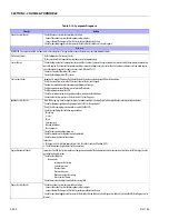
Fuel System Checks
² Check for a restricted fuel filter, contaminated fuel, or improper fuel pressure. Refer to LPG Fuel System Diagnosis.
² Check for the proper ignition output voltage with the spark tester J 26792 or the equivalent.
² Check for proper installation of the mixer module assembly.
² Check all air inlet ducts for condition and proper installation.
² Check for fuel leaks between the LPR and the mixer.
² Verify that the LPG tank manual shut-off valve is fully open.
² Verify that liquid fuel (not vapor) is being delivered to the LPR.
Sensor Checks
² Check the Heated Exhaust Gas Oxygen Sensor (HEGO) for contamination and performance. Check for proper operation of the MAP sensor.
² Check for proper operation of the TPS sensor.
Exhaust System Checks
² Check the exhaust system for a possible restriction:
- Inspect the exhaust system for damaged or collapsed pipes
- Inspect the muffler for signs of heat distress or for possible internal failure.
- Check for possible plugged catalytic converter.
Engine Mechanical Check
Check the engine for the following:
² Engine compression
² Valve timing
² Improper or worn camshaft. Refer to Engine Mechanical in the Service Manual.
Additional Check
² Check the ECM grounds for being clean, tight, and in their proper locations.
² Check the generator output voltage.
² If all procedures have been completed and no malfunction has been found, review and inspect the following items:
² Visually and physically, inspect all electrical connections within the suspected circuit and/or systems.
² Check the scan tool data.
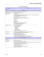
Poor Fuel Economy
DEFINITION: Fuel economy, as measured by refueling records, is noticeably lower than expected. Also, the economy is noticeably lower than it was on this vehicle at one time, as previously
shown by an by refueling records.
Preliminary Checks
² Refer to Important Preliminary Checks.
² Check the air cleaner element (filter) for dirt or being plugged.
² Visually (Physically) check the vacuum hoses for splits, kinks, and proper connections.
² Check the operators driving habits for the following items:
- Is there excessive idling or stop and go driving?
- Are the tires at the correct air pressure?
- Are excessively heavy loads being carried?
- Is their often rapid acceleration?
² Suggest to the owner to fill the fuel tank and to recheck the fuel economy.
² Suggest that a different operator use the equipment and record the results.
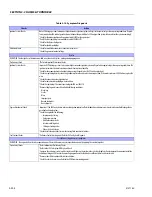
Fuel System Checks
² Check the LPR fuel pressure. Refer to LPG Fuel System Diagnosis.
² Check the fuel system for leakage.
Sensor Checks
² Check the Temperature Manifold Absolute Pressure (TMAP) sensor.
Ignition System Checks
² Verify that the spark plugs are correct for use with LPG (R42LTS)
² Check the spark plugs. Remove the plugs and inspect them for the following conditions:
- Wet plugs
- Cracks
- Wear
- Improper gap
- Burned electrodes
- Heavy deposits
² Check the ignition wires for the following items:
- Cracking
- Hardness
- Proper connections
Cooling System Checks
² Check the engine thermostat for always being open or for the wrong heat range
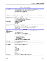
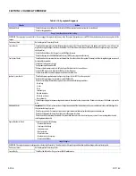
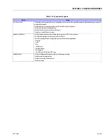
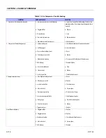
Table 3-15. Symptom Diagnosis
Checks
Action
Содержание 740AJ
Страница 1: ...Service and Maintenance Manual Model 740AJ Prior to S N 0300185827 P N 3121160 October 24 2017 AS NZS...
Страница 2: ......
Страница 51: ...SECTION 2 GENERAL 3121160 2 11 Figure 2 2 Engine Operating Temperature Specifications Ford 4150548 E...
Страница 55: ...SECTION 3 CHASSIS TURNTABLE 3121160 3 3 This page left blank intentionally...
Страница 56: ...SECTION 3 CHASSIS TURNTABLE 3 4 3121160 1 Figure 3 2 Axle and Steering Installation Sheet 1 of 2 0258286 C...
Страница 100: ...SECTION 3 CHASSIS TURNTABLE 3 48 3121160 Figure 3 37 Swing Bearing Tolerance Boom Placement Sheet 1 of 2...
Страница 101: ...SECTION 3 CHASSIS TURNTABLE 3121160 3 49 Figure 3 38 Swing Bearing Tolerance Boom Placement Sheet 2 of 2...
Страница 116: ...SECTION 3 CHASSIS TURNTABLE 3 64 3121160 Figure 3 44 Swing Hub Prior to SN 0300074383...
Страница 124: ...SECTION 3 CHASSIS TURNTABLE 3 72 3121160 Figure 3 45 Swing Drive Hub Fairfield SN 0300074383 through 0300134352...
Страница 180: ...SECTION 3 CHASSIS TURNTABLE 3 128 3121160 1 Figure 3 66 Auxiliary Pump Location 1 AuxiliaryPump 2 HydraulicTank...
Страница 203: ...SECTION 3 CHASSIS TURNTABLE 3121160 3 151 Figure 3 77 EFI Component Location...
Страница 206: ...SECTION 3 CHASSIS TURNTABLE 3 154 3121160 Figure 3 78 ECM EPM Identification ECM EPM...
Страница 213: ...SECTION 3 CHASSIS TURNTABLE 3121160 3 161 Megajector Regulator LockoffSolenoid Figure 3 80 LPG System Components Mixer...
Страница 219: ...SECTION 3 CHASSIS TURNTABLE 3121160 3 167 Figure 3 81 Check Out and Initial Start Up Procedures...
Страница 224: ...SECTION 3 CHASSIS TURNTABLE 3 172 3121160 Figure 3 83 Deutz EMR 2 Troubleshooting Flow Chart...
Страница 225: ...SECTION 3 CHASSIS TURNTABLE 3121160 3 173 Figure 3 84 Deutz EMR 2 Vehicle Side Connection Diagram...
Страница 226: ...SECTION 3 CHASSIS TURNTABLE 3 174 3121160 Figure 3 85 Deutz EMR 2 Engine Side Connection Diagram Sheet 1 of 2...
Страница 227: ...SECTION 3 CHASSIS TURNTABLE 3121160 3 175 Figure 3 86 Deutz EMR 2 Engine Side Connection Diagram Sheet 2 of 2...
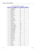
Страница 228: ...SECTION 3 CHASSIS TURNTABLE 3 176 3121160 Figure 3 87 EMR 2 Engine Plug Pin Identification...
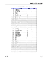
Страница 229: ...SECTION 3 CHASSIS TURNTABLE 3121160 3 177 Figure 3 88 EMR 2 Vehicle Plug Pin Identification...
Страница 230: ...SECTION 3 CHASSIS TURNTABLE 3 178 3121160 Figure 3 89 EMR2 Fault Codes Sheet 1 of 5...
Страница 231: ...SECTION 3 CHASSIS TURNTABLE 3121160 3 179 Figure 3 90 EMR2 Fault Codes Sheet 2 of 5...
Страница 232: ...SECTION 3 CHASSIS TURNTABLE 3 180 3121160 Figure 3 91 EMR2 Fault Codes Sheet 3 of 5...
Страница 233: ...SECTION 3 CHASSIS TURNTABLE 3121160 3 181 Figure 3 92 EMR2 Fault Codes Sheet 4 of 5...
Страница 234: ...SECTION 3 CHASSIS TURNTABLE 3 182 3121160 Figure 3 93 EMR2 Fault Codes Sheet 5 of 5...
Страница 303: ...SECTION 4 BOOM PLATFORM 3121160 4 31 Figure 4 20 Rotator Assembly HELAC...
Страница 335: ...SECTION 4 BOOM PLATFORM 3121160 4 63 THIS SENSOR ON NON ADE MACHINES ONLY Figure 4 27 UMS Sensor Location...
Страница 336: ...SECTION 4 BOOM PLATFORM 4 64 3121160 Figure 4 28 UMS Module Location ADE MACHINES NON ADE MACHINES...
Страница 425: ...SECTION 5 BASIC HYDRAULIC INFORMATION AND SCHEMATICS 3121160 5 81 Figure 5 131 Variable Displacement Pump Rexroth...
Страница 443: ...SECTION 5 BASIC HYDRAULIC INFORMATION AND SCHEMATICS 3121160 5 99 Figure 5 146 Fault Logic Troubleshooting...
Страница 444: ...SECTION 5 BASIC HYDRAULIC INFORMATION AND SCHEMATICS 5 100 3121160 Figure 5 147 Fault Logic Troubleshooting...
Страница 445: ...SECTION 5 BASIC HYDRAULIC INFORMATION AND SCHEMATICS 3121160 5 101 Figure 5 148 Fault Logic Troubleshooting...
Страница 460: ...SECTION 5 BASIC HYDRAULIC INFORMATION AND SCHEMATICS 5 116 3121160 NOTES...
Страница 467: ...SECTION 6 JLG CONTROL SYSTEM 3121160 6 7 Figure 6 2 ADE Block Diagram...
Страница 471: ...SECTION 6 JLG CONTROL SYSTEM 3121160 6 11 Figure 6 6 Analyzer Flow Chart Prior to Version 5 X Software Sheet 4 of 4...
Страница 473: ...SECTION 6 JLG CONTROL SYSTEM 3121160 6 13 Figure 6 8 Analyzer Flow Chart Version 5 X Software Sheet 2 of 4...
Страница 534: ...SECTION 6 JLG CONTROL SYSTEM 6 74 3121160 NOTES...
Страница 545: ...SECTION 7 BASIC ELECTRICAL INFORMATION SCHEMATICS 3121160 7 11 Figure 7 15 Connector Installation...
Страница 580: ...SECTION 7 BASIC ELECTRICAL INFORMATION SCHEMATICS 7 46 3121160 NOTES...
Страница 581: ......

