


SECTION 5 - BASIC HYDRAULIC INFOR
M
ATION AND SCHE
M
ATICS
5-78
3121160
5.10
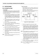
HYDRAULIC OIL CHANGE-OUT PROCEDURE
This procedure is written to change out JLG std. hydraulic oil
(Mobile 424) to cold weather fluid for machines operating in
temperatures exceeding -20°F. (-29°C.). JLG recommends
(Mobile DTE 10). This procedure also applies to change-out of
cold weather oil to std. Mobil 424 hydraulic oil.
NOTE:
This is not a procedure for changing from a petroleum
based fluid to a water based fluid. Stricter guidelines are
required when fluids are not compatable.
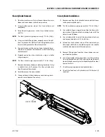
1.
All booms stowed, (jib also), drain the hydraulic oil tank,
(approx. 40 gallons (150 L)).
2.
Disconnect the main drive lines (A & B) from the right
rear drive motor, and right front motor if 4 wheel drive.
Drain into a container.
3.
Disconnect the case drain lines from each of these
motors and drain. This will drain most of the drive sys-
tem. After they have been drained, reconnect them.
4.
Refill the hydraulic oil tank with the appropriate fluid as
recommended.
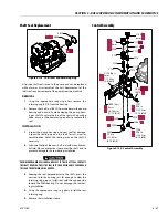
5.
Remove the o-ring plug, (#10 size) on top of the Rexroth
load sense pump. The plug is removed until the oil flows
out of the pump. This insures that the pump cases are
full of oil before starting. Install the plug after there is a
steady flow of oil.
6.
Jog the Auxiliary power pump 2-3 times (not energizing
a function, only the Aux. Pump switch). Then activate
the Aux. switch for approx. 20 seconds. This will flush the
Aux. system.
7.
Start the engine and let idle for a couple of minutes.
Shut off engine.
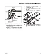
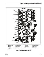
8.
If the machine has a jib: Remove the hose connected to
port #17 on the main valve block and drain into a con-
tainer that will hold at least 2 gallons (8 L) of oil. Plug
port #17. Start the engine and activate jib up to the end
of stroke. Stop, reconnect the hose to port#17, and cycle
the jib function.
9.
Remove the hose at port #8 on the main valve block.
Place this hose inside a container that will hold approx
10 gallons (38 L). Activate tower lift up to the end of
stroke. Reconnect the hose on port #8 and lower the
tower boom.
NOTE:
Depending on the ceiling height, the upper boom might
have to be lowered while lifting the tower.
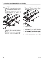
10.
Locate the manual pull valve on the side of the oil tank
(red knob). Disconnect the 1/4" hose (port #1) where it
connects to the side of the hyd. return filter (plug the
port) and place into a container that will hold approx. 10
gallons (38 L). Start the engine. Pull the red knob and
hold it open, while tower is lifting up. Raise the tower 7-
8 ft. (2-2.5 m) and stop. Release the red knob, and lower
the tower boom. At the end of stroke, hold the switch in
the down position. You will hear a hissing sound coming
from the upright. this is oil being replenished in the
tower circuit. Hold the switch until the sound stops.
(approx. 15-20 secs.) Repeat this procedure 2 more
times. Reconnect port #1 hose to the hyd. return filter.
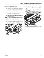
11.
Disconnect the 1/4" hose at the port marked "MT" (plug
the port). Drain the hose into a container that will hold
approx. 2 gallons (8 L). Activate platform rotate and hold
for approx. 60 seconds each direction. Reconnect the
hose to port "MT"
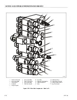
12.
Raise the tower boom to the end of stroke. Disconnect
the hose from port #1 (plug the port) and drain into a
container that will hold approx. 3 gallons (11.5 L). Acti-
vate tower telescope out. At end of stroke, reconnect
the hose and retract the tower telescope cylinder.
13.
Disconnect the hose at port #9 (plug the port), and drain
into a container that will hold approx. 4 gallons. Activate
main telescope out. At end of stroke, reconnect the hose
and retract the telescope function.
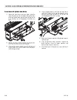
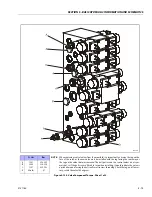
14.
From the ground control, tilt the platform back to the
end of stroke. Turn off the engine. Locate the master cyl-
inder and disconnect the rod end hose (plug the port).
NOTE: THERE WILL BE PRESSURE IN THIS CIRCUIT. Drain
this hose into a container that will hold approx. 2 gal-
lons, and activate platform level down, to end of stroke.
Reconnect hose. Cycle platform level, 2 more times.
Raise the tower boom to full height. Disconnect the
hose at port #12 and drain into a container that will hold
approx. 10 gallons. Activate main lift down to the end of
stroke. Reconnect the hose to port #12. Disconnect the
hose on port #11 (plug the port) and drain into a con-
tainer that will hold approx. 10 gallons (38 L). Activate
lift up to end of stroke. Reconnect the hose to port #11.
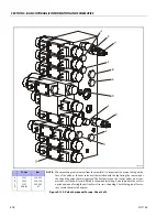
NOTE:
After all functions have been cycled 2-3 times, check the
hydraulic oil tank level.
Содержание 740AJ
Страница 1: ...Service and Maintenance Manual Model 740AJ Prior to S N 0300185827 P N 3121160 October 24 2017 AS NZS...
Страница 2: ......
Страница 51: ...SECTION 2 GENERAL 3121160 2 11 Figure 2 2 Engine Operating Temperature Specifications Ford 4150548 E...
Страница 55: ...SECTION 3 CHASSIS TURNTABLE 3121160 3 3 This page left blank intentionally...
Страница 56: ...SECTION 3 CHASSIS TURNTABLE 3 4 3121160 1 Figure 3 2 Axle and Steering Installation Sheet 1 of 2 0258286 C...
Страница 100: ...SECTION 3 CHASSIS TURNTABLE 3 48 3121160 Figure 3 37 Swing Bearing Tolerance Boom Placement Sheet 1 of 2...
Страница 101: ...SECTION 3 CHASSIS TURNTABLE 3121160 3 49 Figure 3 38 Swing Bearing Tolerance Boom Placement Sheet 2 of 2...
Страница 116: ...SECTION 3 CHASSIS TURNTABLE 3 64 3121160 Figure 3 44 Swing Hub Prior to SN 0300074383...
Страница 124: ...SECTION 3 CHASSIS TURNTABLE 3 72 3121160 Figure 3 45 Swing Drive Hub Fairfield SN 0300074383 through 0300134352...
Страница 180: ...SECTION 3 CHASSIS TURNTABLE 3 128 3121160 1 Figure 3 66 Auxiliary Pump Location 1 AuxiliaryPump 2 HydraulicTank...
Страница 203: ...SECTION 3 CHASSIS TURNTABLE 3121160 3 151 Figure 3 77 EFI Component Location...
Страница 206: ...SECTION 3 CHASSIS TURNTABLE 3 154 3121160 Figure 3 78 ECM EPM Identification ECM EPM...
Страница 213: ...SECTION 3 CHASSIS TURNTABLE 3121160 3 161 Megajector Regulator LockoffSolenoid Figure 3 80 LPG System Components Mixer...
Страница 219: ...SECTION 3 CHASSIS TURNTABLE 3121160 3 167 Figure 3 81 Check Out and Initial Start Up Procedures...
Страница 224: ...SECTION 3 CHASSIS TURNTABLE 3 172 3121160 Figure 3 83 Deutz EMR 2 Troubleshooting Flow Chart...
Страница 225: ...SECTION 3 CHASSIS TURNTABLE 3121160 3 173 Figure 3 84 Deutz EMR 2 Vehicle Side Connection Diagram...
Страница 226: ...SECTION 3 CHASSIS TURNTABLE 3 174 3121160 Figure 3 85 Deutz EMR 2 Engine Side Connection Diagram Sheet 1 of 2...
Страница 227: ...SECTION 3 CHASSIS TURNTABLE 3121160 3 175 Figure 3 86 Deutz EMR 2 Engine Side Connection Diagram Sheet 2 of 2...
Страница 228: ...SECTION 3 CHASSIS TURNTABLE 3 176 3121160 Figure 3 87 EMR 2 Engine Plug Pin Identification...
Страница 229: ...SECTION 3 CHASSIS TURNTABLE 3121160 3 177 Figure 3 88 EMR 2 Vehicle Plug Pin Identification...
Страница 230: ...SECTION 3 CHASSIS TURNTABLE 3 178 3121160 Figure 3 89 EMR2 Fault Codes Sheet 1 of 5...
Страница 231: ...SECTION 3 CHASSIS TURNTABLE 3121160 3 179 Figure 3 90 EMR2 Fault Codes Sheet 2 of 5...
Страница 232: ...SECTION 3 CHASSIS TURNTABLE 3 180 3121160 Figure 3 91 EMR2 Fault Codes Sheet 3 of 5...
Страница 233: ...SECTION 3 CHASSIS TURNTABLE 3121160 3 181 Figure 3 92 EMR2 Fault Codes Sheet 4 of 5...
Страница 234: ...SECTION 3 CHASSIS TURNTABLE 3 182 3121160 Figure 3 93 EMR2 Fault Codes Sheet 5 of 5...
Страница 303: ...SECTION 4 BOOM PLATFORM 3121160 4 31 Figure 4 20 Rotator Assembly HELAC...
Страница 335: ...SECTION 4 BOOM PLATFORM 3121160 4 63 THIS SENSOR ON NON ADE MACHINES ONLY Figure 4 27 UMS Sensor Location...
Страница 336: ...SECTION 4 BOOM PLATFORM 4 64 3121160 Figure 4 28 UMS Module Location ADE MACHINES NON ADE MACHINES...
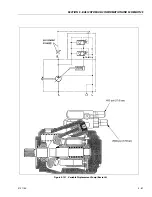
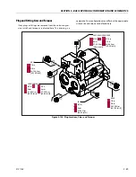
Страница 425: ...SECTION 5 BASIC HYDRAULIC INFORMATION AND SCHEMATICS 3121160 5 81 Figure 5 131 Variable Displacement Pump Rexroth...
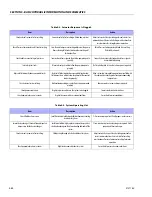
Страница 443: ...SECTION 5 BASIC HYDRAULIC INFORMATION AND SCHEMATICS 3121160 5 99 Figure 5 146 Fault Logic Troubleshooting...
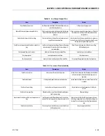
Страница 444: ...SECTION 5 BASIC HYDRAULIC INFORMATION AND SCHEMATICS 5 100 3121160 Figure 5 147 Fault Logic Troubleshooting...
Страница 445: ...SECTION 5 BASIC HYDRAULIC INFORMATION AND SCHEMATICS 3121160 5 101 Figure 5 148 Fault Logic Troubleshooting...
Страница 460: ...SECTION 5 BASIC HYDRAULIC INFORMATION AND SCHEMATICS 5 116 3121160 NOTES...
Страница 467: ...SECTION 6 JLG CONTROL SYSTEM 3121160 6 7 Figure 6 2 ADE Block Diagram...
Страница 471: ...SECTION 6 JLG CONTROL SYSTEM 3121160 6 11 Figure 6 6 Analyzer Flow Chart Prior to Version 5 X Software Sheet 4 of 4...
Страница 473: ...SECTION 6 JLG CONTROL SYSTEM 3121160 6 13 Figure 6 8 Analyzer Flow Chart Version 5 X Software Sheet 2 of 4...
Страница 534: ...SECTION 6 JLG CONTROL SYSTEM 6 74 3121160 NOTES...
Страница 545: ...SECTION 7 BASIC ELECTRICAL INFORMATION SCHEMATICS 3121160 7 11 Figure 7 15 Connector Installation...
Страница 580: ...SECTION 7 BASIC ELECTRICAL INFORMATION SCHEMATICS 7 46 3121160 NOTES...
Страница 581: ......


