SECTION 3 - CHASSIS & TURNTABLE
3121160
3-169
(2.) Incorrect Linkage - Re-check linkage. The freedom of
movement and lack of play are important.
(3.) Incorrect Electrical Hook-up - Re-check all wiring and con-
nections to the Actuator and Controller against the supplied
schematic.
(4.) No speed signal to Controller.
a.
Check the voltage between terminals C and ground
and D and ground of the 8 pin connector with the
engine running. You should see 5 - 30 VDC.
b.
The above checks do not guarantee a good speed
signal, but their absence proves that there is a prob-
lem.
(5.) Incorrect Electrical Hook-up - If steps 1 - 4 above have not
revealed the problem, the governor may have been damaged,
either in shipping or during hook-up and test.
• Governor reacts, but can’t be set up to give proper per-
formance.
This kind of trouble usually falls into three main categories:
1.
Actual Governor malfunction.
2.
Governor installation problems and improper adjust-
ment.
3.
Governor not tuned or adjusted for engine/application.
NOTE:
Assure the engine is operating properly by running engine
manually. The Governor will not control any poor running
engine.
(1.) Actual Governor Malfunction - The Governor was engine-
tested for proper operation just prior to being shipped. Unless
damaged in shipment or by improper handing, it should be
serviceable. To check for proper operation proceed as follows:
a.
Once again, disconnect fuel system linkage from
Governor output arm and control engine manually.
b.
Start engine, hold at a low speed, Governor arm
should move to full-fuel position.
c.
Increase engine speed carefully. At some engine
speed, Governor arm should move to low-fuel posi-
tion.
d.
By carefully varying engine speed, you should be
able to cause the Governor arm to pause momen-
tarily near the middle of its travel. This engine speed
is the speed for which the Governor is adjusted. If
grossly incorrect, reset High Engine Pot.
e.
With the engine running at low speed, move the
Governor arm throughout its stroke by hand. You
should feel a constant smooth force in the on direc-
tion. No binding or rubbing should be felt within
the Governor.
If steps 1a. through 1e. can be accomplished as described, the
Governor is probably OK. It recognizes underspeed, over-
speed, onspeed and is not binding internally.
If the above steps cannot be accomplished satisfactorily, there
is probably an actual Governor malfunction.
a.
Governor is unable to move fuel system freely (not
enough Actuator force available). If Governor
doesn’t move fuel system to on far enough to pro-
vide sufficient fuel but Governor arm moves far
enough when disconnected look for:
1. Linkage binding or misadjusted.
2. Low voltage at Governor during operation.
NOTE:
*Measure the voltage as discussed previously and observe
voltage during operation. If Governor fails to move full on
and voltage dips over 1 volt, check for undersize wire
(should be #16 minimum).
3. Excessive force at Governor during engine running,
particularly on carburetor engines.
NOTE:
*Carburetor butterfly valves are loaded by engine vacuum
during running, which can add considerable force not pres-
ent when engine isn’t running.
NOTE:
*Springs in the system; carburetor return springs, accelera-
tion pump springs, etc., are not usually needed and can
cause governing problems.
b.
Governor is unstable at light-load or no-load. See
“Linkage” for carbureted engines.
c.
Governor experiences sudden, momentary spikes
toward max. at random intervals, then recovers.
1. Look for loose wiring or momentary shorts in wiring.
Noise or occasionally missing speed signal.
d.
Speed seems to slowly wander (5-15 second peri-
ods) around at speed, particularly at higher loads.
See item 2a. 3 concerning excessive on Governor.
(3.) Governor not tuned or adjusted for engine/application.
The basic adjustment to set sensitivity/stability is the Gain pot.
A good starting point for many engines is full CCW, then CW 1/
3 turn. (See “Governor adjustment” section). To increase stabil-
ity, turn CCW. If satisfactory governing cannot be achieved
with this one adjustment, the factory adjustment may be
needed. Normal starting point for this adjustment is fully CCW,
then CW 1/4 turn. (Before changing this pot, mark the original
position).
NOTE:
If problems occurs with the Governor overshooting when a
large load is released from the engine, such as driving up a
hill and stopping. There is usually one of two things:
a.
Gain adjustment is to far CCW.
b.
Mechanical preload between the carburetor and
actuator is to large, this should be no greater than 1/
2 to 1 ball diameter.
Содержание 740AJ
Страница 1: ...Service and Maintenance Manual Model 740AJ Prior to S N 0300185827 P N 3121160 October 24 2017 AS NZS...
Страница 2: ......
Страница 51: ...SECTION 2 GENERAL 3121160 2 11 Figure 2 2 Engine Operating Temperature Specifications Ford 4150548 E...
Страница 55: ...SECTION 3 CHASSIS TURNTABLE 3121160 3 3 This page left blank intentionally...
Страница 56: ...SECTION 3 CHASSIS TURNTABLE 3 4 3121160 1 Figure 3 2 Axle and Steering Installation Sheet 1 of 2 0258286 C...
Страница 100: ...SECTION 3 CHASSIS TURNTABLE 3 48 3121160 Figure 3 37 Swing Bearing Tolerance Boom Placement Sheet 1 of 2...
Страница 101: ...SECTION 3 CHASSIS TURNTABLE 3121160 3 49 Figure 3 38 Swing Bearing Tolerance Boom Placement Sheet 2 of 2...
Страница 116: ...SECTION 3 CHASSIS TURNTABLE 3 64 3121160 Figure 3 44 Swing Hub Prior to SN 0300074383...
Страница 124: ...SECTION 3 CHASSIS TURNTABLE 3 72 3121160 Figure 3 45 Swing Drive Hub Fairfield SN 0300074383 through 0300134352...
Страница 180: ...SECTION 3 CHASSIS TURNTABLE 3 128 3121160 1 Figure 3 66 Auxiliary Pump Location 1 AuxiliaryPump 2 HydraulicTank...
Страница 203: ...SECTION 3 CHASSIS TURNTABLE 3121160 3 151 Figure 3 77 EFI Component Location...
Страница 206: ...SECTION 3 CHASSIS TURNTABLE 3 154 3121160 Figure 3 78 ECM EPM Identification ECM EPM...
Страница 213: ...SECTION 3 CHASSIS TURNTABLE 3121160 3 161 Megajector Regulator LockoffSolenoid Figure 3 80 LPG System Components Mixer...
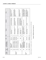
Страница 219: ...SECTION 3 CHASSIS TURNTABLE 3121160 3 167 Figure 3 81 Check Out and Initial Start Up Procedures...
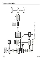
Страница 224: ...SECTION 3 CHASSIS TURNTABLE 3 172 3121160 Figure 3 83 Deutz EMR 2 Troubleshooting Flow Chart...
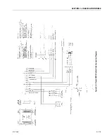
Страница 225: ...SECTION 3 CHASSIS TURNTABLE 3121160 3 173 Figure 3 84 Deutz EMR 2 Vehicle Side Connection Diagram...
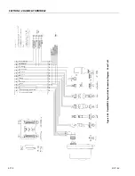
Страница 226: ...SECTION 3 CHASSIS TURNTABLE 3 174 3121160 Figure 3 85 Deutz EMR 2 Engine Side Connection Diagram Sheet 1 of 2...
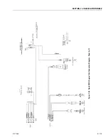
Страница 227: ...SECTION 3 CHASSIS TURNTABLE 3121160 3 175 Figure 3 86 Deutz EMR 2 Engine Side Connection Diagram Sheet 2 of 2...
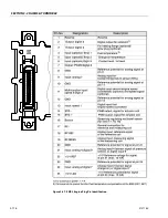
Страница 228: ...SECTION 3 CHASSIS TURNTABLE 3 176 3121160 Figure 3 87 EMR 2 Engine Plug Pin Identification...
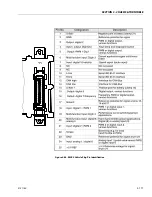
Страница 229: ...SECTION 3 CHASSIS TURNTABLE 3121160 3 177 Figure 3 88 EMR 2 Vehicle Plug Pin Identification...
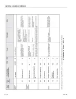
Страница 230: ...SECTION 3 CHASSIS TURNTABLE 3 178 3121160 Figure 3 89 EMR2 Fault Codes Sheet 1 of 5...
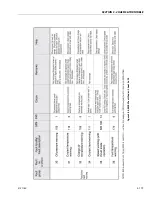
Страница 231: ...SECTION 3 CHASSIS TURNTABLE 3121160 3 179 Figure 3 90 EMR2 Fault Codes Sheet 2 of 5...
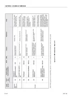
Страница 232: ...SECTION 3 CHASSIS TURNTABLE 3 180 3121160 Figure 3 91 EMR2 Fault Codes Sheet 3 of 5...
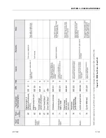
Страница 233: ...SECTION 3 CHASSIS TURNTABLE 3121160 3 181 Figure 3 92 EMR2 Fault Codes Sheet 4 of 5...
Страница 234: ...SECTION 3 CHASSIS TURNTABLE 3 182 3121160 Figure 3 93 EMR2 Fault Codes Sheet 5 of 5...
Страница 303: ...SECTION 4 BOOM PLATFORM 3121160 4 31 Figure 4 20 Rotator Assembly HELAC...
Страница 335: ...SECTION 4 BOOM PLATFORM 3121160 4 63 THIS SENSOR ON NON ADE MACHINES ONLY Figure 4 27 UMS Sensor Location...
Страница 336: ...SECTION 4 BOOM PLATFORM 4 64 3121160 Figure 4 28 UMS Module Location ADE MACHINES NON ADE MACHINES...
Страница 425: ...SECTION 5 BASIC HYDRAULIC INFORMATION AND SCHEMATICS 3121160 5 81 Figure 5 131 Variable Displacement Pump Rexroth...
Страница 443: ...SECTION 5 BASIC HYDRAULIC INFORMATION AND SCHEMATICS 3121160 5 99 Figure 5 146 Fault Logic Troubleshooting...
Страница 444: ...SECTION 5 BASIC HYDRAULIC INFORMATION AND SCHEMATICS 5 100 3121160 Figure 5 147 Fault Logic Troubleshooting...
Страница 445: ...SECTION 5 BASIC HYDRAULIC INFORMATION AND SCHEMATICS 3121160 5 101 Figure 5 148 Fault Logic Troubleshooting...
Страница 460: ...SECTION 5 BASIC HYDRAULIC INFORMATION AND SCHEMATICS 5 116 3121160 NOTES...
Страница 467: ...SECTION 6 JLG CONTROL SYSTEM 3121160 6 7 Figure 6 2 ADE Block Diagram...
Страница 471: ...SECTION 6 JLG CONTROL SYSTEM 3121160 6 11 Figure 6 6 Analyzer Flow Chart Prior to Version 5 X Software Sheet 4 of 4...
Страница 473: ...SECTION 6 JLG CONTROL SYSTEM 3121160 6 13 Figure 6 8 Analyzer Flow Chart Version 5 X Software Sheet 2 of 4...
Страница 534: ...SECTION 6 JLG CONTROL SYSTEM 6 74 3121160 NOTES...
Страница 545: ...SECTION 7 BASIC ELECTRICAL INFORMATION SCHEMATICS 3121160 7 11 Figure 7 15 Connector Installation...
Страница 580: ...SECTION 7 BASIC ELECTRICAL INFORMATION SCHEMATICS 7 46 3121160 NOTES...
Страница 581: ......


