


SECTION 3 - CHASSIS & TURNTABLE
3-152
3121160
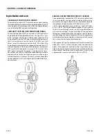
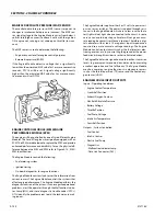
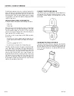
MANIFOLD ABSOLUTE PRESSURE (MAP) SENSOR
The manifold absolute pressure (MAP) sensor responds to
changes in intake manifold pressure (vacuum). The MAP sen-
sor signal voltage to the Engine Module varies from below 2
volts at idle (high vacuum) to above 4 volts with the ignition
ON, engine not running or at wide-open throttle (low vac-
uum).
The MAP sensor is used to determine the following:
• Engine vacuum level for engine control purposes.
• Barometric pressure (BARO)
If the Engine Module detects a voltage that is significantly
lower than the estimated MAP value for 2 or more consecutive
seconds, DTC 14 will be set. A signal voltage significantly
higher than the estimated MAP value for 2 or more consecu-
tive seconds will set DTC 24.
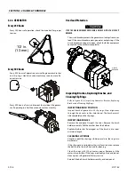
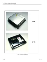
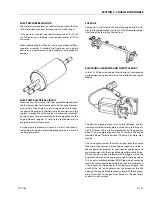
ENGINE CONTROL MODULE (ECM)/ENGINE
PERFORMANCE MODULE (EPM)
The engine will be controlled by one of two different Engine
Modules. The Ford EFI engine was originally equipped with an
ECM. The EPM was developed to replace the ECM and provide
enhanced performance and durability. To see the physical dif-
ference between the ECM and EPM, refer to Figure 3-78., ECM/
EPM Identification.
The Engine Module controls the following:
• Fuel metering system
• Ignition timing
• On-board diagnostics for engine functions
The Engine Module constantly observes the information from
various sensors. The Engine Module controls the systems that
affect engine performance. The Engine Module performs the
diagnostic function of the system. It can recognize operational
problems, alert the operator through the Malfunction Indica-
tor Lamp (MIL), and store diagnostic trouble codes (DTCs).
DTCs identify the problem areas to aid the technician in mak-
ing repairs.
The Engine Module supplies either 5 or 12 volts to power vari-
ous sensors or switches. The power is supplied through resis-
tances in the Engine Module which are so low in value that a
test light will not light when connected to the circuit. In some
cases, even an ordinary shop voltmeter will not give an accu-
rate reading because its resistance is too low. Therefore, a digi-
tal voltmeter with at least 10 meg ohms input impedance is
required to ensure accurate voltage readings. The Engine
Module controls output circuits such as the fuel injectors, elec-
tronic governor, etc., by control ling the ground or the power
feed circuit through transistors or other solid state devices.
The Engine Module is designed to maintain exhaust emission
levels to government mandated standards while providing
excellent operation and fuel efficiency. The Engine Module
monitors numerous engine functions via electronic sensors
such as the throttle position (TP) sensor and the heated oxy-
gen sensor (HO2S).
ENGINE MODULE INPUTS/OUTPUTS
Inputs - Operating Conditions
• Engine Coolant Temperature
• Crankshaft Position
• Exhaust Oxygen Content
• Manifold Absolute Pressure
• Battery Voltage
• Throttle Position
• Fuel Pump Voltage
• Intake Air Temperature
• Camshaft Position
Outputs - System Controlled
• Fuel Control
• Idle Air Control
• Electric Fuel Pump
• Diagnostics:
- Malfunction Indicator Lamp
- Data Link Connector (DLC)
Содержание 740AJ
Страница 1: ...Service and Maintenance Manual Model 740AJ Prior to S N 0300185827 P N 3121160 October 24 2017 AS NZS...
Страница 2: ......
Страница 51: ...SECTION 2 GENERAL 3121160 2 11 Figure 2 2 Engine Operating Temperature Specifications Ford 4150548 E...
Страница 55: ...SECTION 3 CHASSIS TURNTABLE 3121160 3 3 This page left blank intentionally...
Страница 56: ...SECTION 3 CHASSIS TURNTABLE 3 4 3121160 1 Figure 3 2 Axle and Steering Installation Sheet 1 of 2 0258286 C...
Страница 100: ...SECTION 3 CHASSIS TURNTABLE 3 48 3121160 Figure 3 37 Swing Bearing Tolerance Boom Placement Sheet 1 of 2...
Страница 101: ...SECTION 3 CHASSIS TURNTABLE 3121160 3 49 Figure 3 38 Swing Bearing Tolerance Boom Placement Sheet 2 of 2...
Страница 116: ...SECTION 3 CHASSIS TURNTABLE 3 64 3121160 Figure 3 44 Swing Hub Prior to SN 0300074383...
Страница 124: ...SECTION 3 CHASSIS TURNTABLE 3 72 3121160 Figure 3 45 Swing Drive Hub Fairfield SN 0300074383 through 0300134352...
Страница 180: ...SECTION 3 CHASSIS TURNTABLE 3 128 3121160 1 Figure 3 66 Auxiliary Pump Location 1 AuxiliaryPump 2 HydraulicTank...
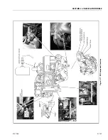
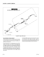
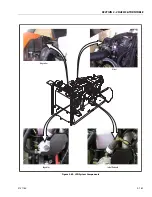
Страница 203: ...SECTION 3 CHASSIS TURNTABLE 3121160 3 151 Figure 3 77 EFI Component Location...
Страница 206: ...SECTION 3 CHASSIS TURNTABLE 3 154 3121160 Figure 3 78 ECM EPM Identification ECM EPM...
Страница 213: ...SECTION 3 CHASSIS TURNTABLE 3121160 3 161 Megajector Regulator LockoffSolenoid Figure 3 80 LPG System Components Mixer...
Страница 219: ...SECTION 3 CHASSIS TURNTABLE 3121160 3 167 Figure 3 81 Check Out and Initial Start Up Procedures...
Страница 224: ...SECTION 3 CHASSIS TURNTABLE 3 172 3121160 Figure 3 83 Deutz EMR 2 Troubleshooting Flow Chart...
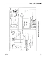
Страница 225: ...SECTION 3 CHASSIS TURNTABLE 3121160 3 173 Figure 3 84 Deutz EMR 2 Vehicle Side Connection Diagram...
Страница 226: ...SECTION 3 CHASSIS TURNTABLE 3 174 3121160 Figure 3 85 Deutz EMR 2 Engine Side Connection Diagram Sheet 1 of 2...
Страница 227: ...SECTION 3 CHASSIS TURNTABLE 3121160 3 175 Figure 3 86 Deutz EMR 2 Engine Side Connection Diagram Sheet 2 of 2...
Страница 228: ...SECTION 3 CHASSIS TURNTABLE 3 176 3121160 Figure 3 87 EMR 2 Engine Plug Pin Identification...
Страница 229: ...SECTION 3 CHASSIS TURNTABLE 3121160 3 177 Figure 3 88 EMR 2 Vehicle Plug Pin Identification...
Страница 230: ...SECTION 3 CHASSIS TURNTABLE 3 178 3121160 Figure 3 89 EMR2 Fault Codes Sheet 1 of 5...
Страница 231: ...SECTION 3 CHASSIS TURNTABLE 3121160 3 179 Figure 3 90 EMR2 Fault Codes Sheet 2 of 5...
Страница 232: ...SECTION 3 CHASSIS TURNTABLE 3 180 3121160 Figure 3 91 EMR2 Fault Codes Sheet 3 of 5...
Страница 233: ...SECTION 3 CHASSIS TURNTABLE 3121160 3 181 Figure 3 92 EMR2 Fault Codes Sheet 4 of 5...
Страница 234: ...SECTION 3 CHASSIS TURNTABLE 3 182 3121160 Figure 3 93 EMR2 Fault Codes Sheet 5 of 5...
Страница 303: ...SECTION 4 BOOM PLATFORM 3121160 4 31 Figure 4 20 Rotator Assembly HELAC...
Страница 335: ...SECTION 4 BOOM PLATFORM 3121160 4 63 THIS SENSOR ON NON ADE MACHINES ONLY Figure 4 27 UMS Sensor Location...
Страница 336: ...SECTION 4 BOOM PLATFORM 4 64 3121160 Figure 4 28 UMS Module Location ADE MACHINES NON ADE MACHINES...
Страница 425: ...SECTION 5 BASIC HYDRAULIC INFORMATION AND SCHEMATICS 3121160 5 81 Figure 5 131 Variable Displacement Pump Rexroth...
Страница 443: ...SECTION 5 BASIC HYDRAULIC INFORMATION AND SCHEMATICS 3121160 5 99 Figure 5 146 Fault Logic Troubleshooting...
Страница 444: ...SECTION 5 BASIC HYDRAULIC INFORMATION AND SCHEMATICS 5 100 3121160 Figure 5 147 Fault Logic Troubleshooting...
Страница 445: ...SECTION 5 BASIC HYDRAULIC INFORMATION AND SCHEMATICS 3121160 5 101 Figure 5 148 Fault Logic Troubleshooting...
Страница 460: ...SECTION 5 BASIC HYDRAULIC INFORMATION AND SCHEMATICS 5 116 3121160 NOTES...
Страница 467: ...SECTION 6 JLG CONTROL SYSTEM 3121160 6 7 Figure 6 2 ADE Block Diagram...
Страница 471: ...SECTION 6 JLG CONTROL SYSTEM 3121160 6 11 Figure 6 6 Analyzer Flow Chart Prior to Version 5 X Software Sheet 4 of 4...
Страница 473: ...SECTION 6 JLG CONTROL SYSTEM 3121160 6 13 Figure 6 8 Analyzer Flow Chart Version 5 X Software Sheet 2 of 4...
Страница 534: ...SECTION 6 JLG CONTROL SYSTEM 6 74 3121160 NOTES...
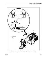
Страница 545: ...SECTION 7 BASIC ELECTRICAL INFORMATION SCHEMATICS 3121160 7 11 Figure 7 15 Connector Installation...
Страница 580: ...SECTION 7 BASIC ELECTRICAL INFORMATION SCHEMATICS 7 46 3121160 NOTES...
Страница 581: ......


