


SECTION 3 - CHASSIS & TURNTABLE
3121160
3-145
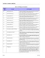
211
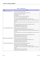
IAT High Voltage
This fault will set if the signal voltage is more than 4.95 volts anytime the engine is running. The EPM
will use the default value for the IAT sensor in the event of this fault.
212
IAT Low Voltage
This fault will set if the signal voltage is less than 0.05 volts anytime the engine is cranking or running.
The EPM will use a default value for the IAT sensor in the event
213
IAT Higher Than Expected 1
This fault will set if the Intake Air Temperature is greater than 200 °F and engine RPM is greater than
1000 and Power Derate 1 will be enforced. During this fault, maximum throttle position is 50% and the
MIL light will flash twice per second.
214
IAT Higher Than Expected 2
This fault will set if the Intake Air Temperature is greater than 210 °F and engine RPM is greater than
1000. The MIL light will be on during this active fault and the engine will shut down.
215
Oil Pressure Low
This fault can be configured two different ways. It may use a normally closed switch or a normally open
switch. If the switch is normally open, the fault will set if the circuit becomes grounded. If the switch is
normally closed, the fault will set if the circuit becomes open. Go to the Fault page on Diagnostic Tool to
determine how the input is configured. (“Open is OK” is normally open and “Ground is OK” is normally
closed). The engine will shut down in the event of this fault to help prevent possible damage.
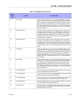
221
ECT High Voltage
This fault will set if the signal voltage is greater than 4.95 volts anytime the engine is running. The EPM
will use a default value for the ECT sensor in the event of this fault.
222
ECT Low Voltage
This fault will set if the signal voltage is less than 0.05 volts anytime the engine is running. The EPM will
use a default value for the ECT sensor in the event of this fault.
231
MAP High Pressure
This fault will set when the MAP reading is higher than it should be for the given TPS, and RPM. When
the fault is set, the Adaptive Learn will be disabled for the remainder of the key on cycle and the MIL
will be on. The engine will operate on a default MAP during this active fault.
232
MAP Low Voltage
This fault will set when the MAP reading is lower than the sensor should normally produce. When this
fault is set the Adaptive learn will be disabled for the remainder of the key on cycle and the MIL will be
on.
234
BP High Pressure
This fault sets in the event the BP value is out of the normal range.
235
BP Low Pressure
This fault sets in the event the BP value is out of the normal range.
242
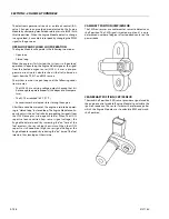
Crank Sync Noise
The EPM must see a valid Crankshaft position signal while running. If no signal is present for 800 ms or
longer, this fault will set.
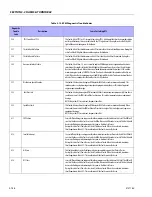
243
Never Crank Synced At Start
The EPM must see a valid Crankshaft Position signal while cranking before it starts. If no signal is pres-
ent within 4 cranking revs, this fault will set.
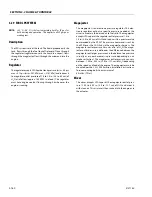
244
Camshaft Sensor Loss
The Camshaft Position Sensor is used to determine which cylinder to fire. This fault will set if the EPM
does not detect a cam pulse when the RPM is greater than 1000. Normally the engine will run with this
fault present. In some instances this fault may cause rough engine operation.
245
Camshaft Sensor Noise
This fault will set if the EPM detects erroneous pulses from the camshaft position sensor causing
invalid cam re-sync.
253
Knock Sensor Open
This fault will set if the Knock Sensor input to the EPM is less than 0.2 volt while engine rpm is greater
than 1500 and MAP is greater than 8 psia.
254
Excessive Knock Signal
This fault will set if the Knock Sensor input to the EPM is greater than 4.5 volts while MAP is less than 8
psia and knock spark retard is at maximum.
Table 3-13. EPM Diagnostic Trouble Codes
Diagnostic
Trouble
Code
Description
Cause for Setting DTC
Содержание 740AJ
Страница 1: ...Service and Maintenance Manual Model 740AJ Prior to S N 0300185827 P N 3121160 October 24 2017 AS NZS...
Страница 2: ......
Страница 51: ...SECTION 2 GENERAL 3121160 2 11 Figure 2 2 Engine Operating Temperature Specifications Ford 4150548 E...
Страница 55: ...SECTION 3 CHASSIS TURNTABLE 3121160 3 3 This page left blank intentionally...
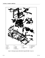
Страница 56: ...SECTION 3 CHASSIS TURNTABLE 3 4 3121160 1 Figure 3 2 Axle and Steering Installation Sheet 1 of 2 0258286 C...
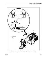
Страница 100: ...SECTION 3 CHASSIS TURNTABLE 3 48 3121160 Figure 3 37 Swing Bearing Tolerance Boom Placement Sheet 1 of 2...
Страница 101: ...SECTION 3 CHASSIS TURNTABLE 3121160 3 49 Figure 3 38 Swing Bearing Tolerance Boom Placement Sheet 2 of 2...
Страница 116: ...SECTION 3 CHASSIS TURNTABLE 3 64 3121160 Figure 3 44 Swing Hub Prior to SN 0300074383...
Страница 124: ...SECTION 3 CHASSIS TURNTABLE 3 72 3121160 Figure 3 45 Swing Drive Hub Fairfield SN 0300074383 through 0300134352...
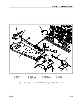
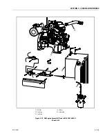
Страница 180: ...SECTION 3 CHASSIS TURNTABLE 3 128 3121160 1 Figure 3 66 Auxiliary Pump Location 1 AuxiliaryPump 2 HydraulicTank...
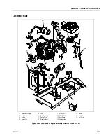
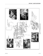
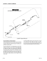
Страница 203: ...SECTION 3 CHASSIS TURNTABLE 3121160 3 151 Figure 3 77 EFI Component Location...
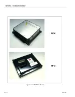
Страница 206: ...SECTION 3 CHASSIS TURNTABLE 3 154 3121160 Figure 3 78 ECM EPM Identification ECM EPM...
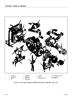
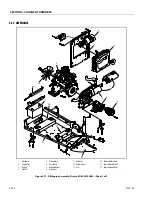
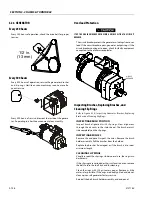
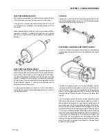
Страница 213: ...SECTION 3 CHASSIS TURNTABLE 3121160 3 161 Megajector Regulator LockoffSolenoid Figure 3 80 LPG System Components Mixer...
Страница 219: ...SECTION 3 CHASSIS TURNTABLE 3121160 3 167 Figure 3 81 Check Out and Initial Start Up Procedures...
Страница 224: ...SECTION 3 CHASSIS TURNTABLE 3 172 3121160 Figure 3 83 Deutz EMR 2 Troubleshooting Flow Chart...
Страница 225: ...SECTION 3 CHASSIS TURNTABLE 3121160 3 173 Figure 3 84 Deutz EMR 2 Vehicle Side Connection Diagram...
Страница 226: ...SECTION 3 CHASSIS TURNTABLE 3 174 3121160 Figure 3 85 Deutz EMR 2 Engine Side Connection Diagram Sheet 1 of 2...
Страница 227: ...SECTION 3 CHASSIS TURNTABLE 3121160 3 175 Figure 3 86 Deutz EMR 2 Engine Side Connection Diagram Sheet 2 of 2...
Страница 228: ...SECTION 3 CHASSIS TURNTABLE 3 176 3121160 Figure 3 87 EMR 2 Engine Plug Pin Identification...
Страница 229: ...SECTION 3 CHASSIS TURNTABLE 3121160 3 177 Figure 3 88 EMR 2 Vehicle Plug Pin Identification...
Страница 230: ...SECTION 3 CHASSIS TURNTABLE 3 178 3121160 Figure 3 89 EMR2 Fault Codes Sheet 1 of 5...
Страница 231: ...SECTION 3 CHASSIS TURNTABLE 3121160 3 179 Figure 3 90 EMR2 Fault Codes Sheet 2 of 5...
Страница 232: ...SECTION 3 CHASSIS TURNTABLE 3 180 3121160 Figure 3 91 EMR2 Fault Codes Sheet 3 of 5...
Страница 233: ...SECTION 3 CHASSIS TURNTABLE 3121160 3 181 Figure 3 92 EMR2 Fault Codes Sheet 4 of 5...
Страница 234: ...SECTION 3 CHASSIS TURNTABLE 3 182 3121160 Figure 3 93 EMR2 Fault Codes Sheet 5 of 5...
Страница 303: ...SECTION 4 BOOM PLATFORM 3121160 4 31 Figure 4 20 Rotator Assembly HELAC...
Страница 335: ...SECTION 4 BOOM PLATFORM 3121160 4 63 THIS SENSOR ON NON ADE MACHINES ONLY Figure 4 27 UMS Sensor Location...
Страница 336: ...SECTION 4 BOOM PLATFORM 4 64 3121160 Figure 4 28 UMS Module Location ADE MACHINES NON ADE MACHINES...
Страница 425: ...SECTION 5 BASIC HYDRAULIC INFORMATION AND SCHEMATICS 3121160 5 81 Figure 5 131 Variable Displacement Pump Rexroth...
Страница 443: ...SECTION 5 BASIC HYDRAULIC INFORMATION AND SCHEMATICS 3121160 5 99 Figure 5 146 Fault Logic Troubleshooting...
Страница 444: ...SECTION 5 BASIC HYDRAULIC INFORMATION AND SCHEMATICS 5 100 3121160 Figure 5 147 Fault Logic Troubleshooting...
Страница 445: ...SECTION 5 BASIC HYDRAULIC INFORMATION AND SCHEMATICS 3121160 5 101 Figure 5 148 Fault Logic Troubleshooting...
Страница 460: ...SECTION 5 BASIC HYDRAULIC INFORMATION AND SCHEMATICS 5 116 3121160 NOTES...
Страница 467: ...SECTION 6 JLG CONTROL SYSTEM 3121160 6 7 Figure 6 2 ADE Block Diagram...
Страница 471: ...SECTION 6 JLG CONTROL SYSTEM 3121160 6 11 Figure 6 6 Analyzer Flow Chart Prior to Version 5 X Software Sheet 4 of 4...
Страница 473: ...SECTION 6 JLG CONTROL SYSTEM 3121160 6 13 Figure 6 8 Analyzer Flow Chart Version 5 X Software Sheet 2 of 4...
Страница 534: ...SECTION 6 JLG CONTROL SYSTEM 6 74 3121160 NOTES...
Страница 545: ...SECTION 7 BASIC ELECTRICAL INFORMATION SCHEMATICS 3121160 7 11 Figure 7 15 Connector Installation...
Страница 580: ...SECTION 7 BASIC ELECTRICAL INFORMATION SCHEMATICS 7 46 3121160 NOTES...
Страница 581: ......


