


SECTION 3 - CHASSIS & TURNTABLE
3-210
3121160
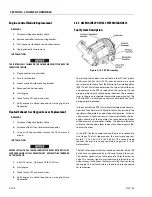
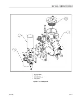
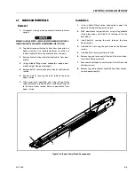
3.36 AIR COMPRESSOR
Description
The compressor consists of a heavy duty rotary screw air com-
pressor with integral inlet valve assembly, oil separation sys-
tem, minimum pressure/discharge check valve and oil filter
housing. The complete system incorporates compressor oil
cooling system, hydraulic drive and valving.
Oil Injection
Lubricant is injected into the compressor air end unit and
mixes directly with the air in the compression chamber, inter-
nal porting also injects oil into the bearings and seal area. The
lubricant has three primary functions:
• Controls the rise of air temperature normally associated
with the heat of compression.
• Seals the leakage paths between the rotors and the stator,
and also between the rotors themselves.
• Acts as a lubricating film between the rotors allowing one
rotor to directly drive the other which is an idler. It also
lubricates the bearings and seal.
The screw compressor assembly is mounted inside the main
casting and consists of a male and female rotor supported
with
anti-friction bearings suitably sized for long life.
Inlet Valve and Control Valving
The inlet valve and control solenoid valve assembly are
mounted directly on top of the compressor module. On initial
start-up the solenoid is energized and the inlet valve opens
from pilot air being passed through the solenoid actuated
valve. When final pressure is reached a pressure switch de-acti-
vates the solenoid and the inlet valve
closes
.
At the same time
the compressor pressure will relieve down to a low pressure
(typically about 40 psig (2.75 bar)). Only the compressed air
within the compressor module will reduce down to this lower
pressure due to the operation of the discharge minimum pres-
sure/check valve. This reduction in internal air pressure
reduces the power requirement considerably during this
unloaded state. The pressure switch located in the down-
stream air line senses air demand and upon reducing pressure
in discharge line (ie. air being used) will re-activate the inlet
valve and the compressor again starts to load and produce air.
The discharge air pressure switch will typically
be set with a
30
psi (2.0 bar) differential pressure.
Air Filter Unit
The air filter is dry type replaceable element and is mounted
directly on top of the inlet valve assembly. The element is eas-
ily replaced for service changeout - Refer to Maintenance Sec-
tion.
Oil Reservoir and Primary Oil Separation
The main casting which contains the screw compressor is also
the oil reservoir and primary oil separation unit. The initial (pri-
mary) oil separation is caused by both changes in velocity and
direction. The main casting also contains the oil level/fill plug
and oil drain connection. A separate oil reservoir is not
required.
Secondary Spin-On Oil Coalescer/Separator
This spin-on element screws directly onto the filter support
housing at the rear of the compressor module. The separator
element (coalescer) recovers the finer particles of residual oil
after pre-separation oil, which is collected in this element is
scavenged back into the compressor unit. The oil return line
passes through the Oil Sight Glass which indicates the amount
of oil being deposited (scavenged) in the element. At start-up
the sight
glass most likely will be full for a short period which is
due to drainage from the element when it is not in use, this
should diminish fairly quickly and a lesser amount should be
observed which indicates that the element is separating out
oil deposited within the spin-on element.
Spin-On Oil Filter
Located on the filter support housing at the rear of the com-
pressor. The filter incorporates a by-pass valve which will open
to by-pass the filter during cold start-up when the oil is very
viscous. It will also open if the filter element is plugged. Filter
element rating is 10 Micron.
Содержание 740AJ
Страница 1: ...Service and Maintenance Manual Model 740AJ Prior to S N 0300185827 P N 3121160 October 24 2017 AS NZS...
Страница 2: ......
Страница 51: ...SECTION 2 GENERAL 3121160 2 11 Figure 2 2 Engine Operating Temperature Specifications Ford 4150548 E...
Страница 55: ...SECTION 3 CHASSIS TURNTABLE 3121160 3 3 This page left blank intentionally...
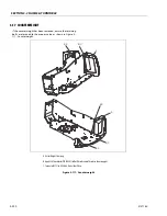
Страница 56: ...SECTION 3 CHASSIS TURNTABLE 3 4 3121160 1 Figure 3 2 Axle and Steering Installation Sheet 1 of 2 0258286 C...
Страница 100: ...SECTION 3 CHASSIS TURNTABLE 3 48 3121160 Figure 3 37 Swing Bearing Tolerance Boom Placement Sheet 1 of 2...
Страница 101: ...SECTION 3 CHASSIS TURNTABLE 3121160 3 49 Figure 3 38 Swing Bearing Tolerance Boom Placement Sheet 2 of 2...
Страница 116: ...SECTION 3 CHASSIS TURNTABLE 3 64 3121160 Figure 3 44 Swing Hub Prior to SN 0300074383...
Страница 124: ...SECTION 3 CHASSIS TURNTABLE 3 72 3121160 Figure 3 45 Swing Drive Hub Fairfield SN 0300074383 through 0300134352...
Страница 180: ...SECTION 3 CHASSIS TURNTABLE 3 128 3121160 1 Figure 3 66 Auxiliary Pump Location 1 AuxiliaryPump 2 HydraulicTank...
Страница 203: ...SECTION 3 CHASSIS TURNTABLE 3121160 3 151 Figure 3 77 EFI Component Location...
Страница 206: ...SECTION 3 CHASSIS TURNTABLE 3 154 3121160 Figure 3 78 ECM EPM Identification ECM EPM...
Страница 213: ...SECTION 3 CHASSIS TURNTABLE 3121160 3 161 Megajector Regulator LockoffSolenoid Figure 3 80 LPG System Components Mixer...
Страница 219: ...SECTION 3 CHASSIS TURNTABLE 3121160 3 167 Figure 3 81 Check Out and Initial Start Up Procedures...
Страница 224: ...SECTION 3 CHASSIS TURNTABLE 3 172 3121160 Figure 3 83 Deutz EMR 2 Troubleshooting Flow Chart...
Страница 225: ...SECTION 3 CHASSIS TURNTABLE 3121160 3 173 Figure 3 84 Deutz EMR 2 Vehicle Side Connection Diagram...
Страница 226: ...SECTION 3 CHASSIS TURNTABLE 3 174 3121160 Figure 3 85 Deutz EMR 2 Engine Side Connection Diagram Sheet 1 of 2...
Страница 227: ...SECTION 3 CHASSIS TURNTABLE 3121160 3 175 Figure 3 86 Deutz EMR 2 Engine Side Connection Diagram Sheet 2 of 2...
Страница 228: ...SECTION 3 CHASSIS TURNTABLE 3 176 3121160 Figure 3 87 EMR 2 Engine Plug Pin Identification...
Страница 229: ...SECTION 3 CHASSIS TURNTABLE 3121160 3 177 Figure 3 88 EMR 2 Vehicle Plug Pin Identification...
Страница 230: ...SECTION 3 CHASSIS TURNTABLE 3 178 3121160 Figure 3 89 EMR2 Fault Codes Sheet 1 of 5...
Страница 231: ...SECTION 3 CHASSIS TURNTABLE 3121160 3 179 Figure 3 90 EMR2 Fault Codes Sheet 2 of 5...
Страница 232: ...SECTION 3 CHASSIS TURNTABLE 3 180 3121160 Figure 3 91 EMR2 Fault Codes Sheet 3 of 5...
Страница 233: ...SECTION 3 CHASSIS TURNTABLE 3121160 3 181 Figure 3 92 EMR2 Fault Codes Sheet 4 of 5...
Страница 234: ...SECTION 3 CHASSIS TURNTABLE 3 182 3121160 Figure 3 93 EMR2 Fault Codes Sheet 5 of 5...
Страница 303: ...SECTION 4 BOOM PLATFORM 3121160 4 31 Figure 4 20 Rotator Assembly HELAC...
Страница 335: ...SECTION 4 BOOM PLATFORM 3121160 4 63 THIS SENSOR ON NON ADE MACHINES ONLY Figure 4 27 UMS Sensor Location...
Страница 336: ...SECTION 4 BOOM PLATFORM 4 64 3121160 Figure 4 28 UMS Module Location ADE MACHINES NON ADE MACHINES...
Страница 425: ...SECTION 5 BASIC HYDRAULIC INFORMATION AND SCHEMATICS 3121160 5 81 Figure 5 131 Variable Displacement Pump Rexroth...
Страница 443: ...SECTION 5 BASIC HYDRAULIC INFORMATION AND SCHEMATICS 3121160 5 99 Figure 5 146 Fault Logic Troubleshooting...
Страница 444: ...SECTION 5 BASIC HYDRAULIC INFORMATION AND SCHEMATICS 5 100 3121160 Figure 5 147 Fault Logic Troubleshooting...
Страница 445: ...SECTION 5 BASIC HYDRAULIC INFORMATION AND SCHEMATICS 3121160 5 101 Figure 5 148 Fault Logic Troubleshooting...
Страница 460: ...SECTION 5 BASIC HYDRAULIC INFORMATION AND SCHEMATICS 5 116 3121160 NOTES...
Страница 467: ...SECTION 6 JLG CONTROL SYSTEM 3121160 6 7 Figure 6 2 ADE Block Diagram...
Страница 471: ...SECTION 6 JLG CONTROL SYSTEM 3121160 6 11 Figure 6 6 Analyzer Flow Chart Prior to Version 5 X Software Sheet 4 of 4...
Страница 473: ...SECTION 6 JLG CONTROL SYSTEM 3121160 6 13 Figure 6 8 Analyzer Flow Chart Version 5 X Software Sheet 2 of 4...
Страница 534: ...SECTION 6 JLG CONTROL SYSTEM 6 74 3121160 NOTES...
Страница 545: ...SECTION 7 BASIC ELECTRICAL INFORMATION SCHEMATICS 3121160 7 11 Figure 7 15 Connector Installation...
Страница 580: ...SECTION 7 BASIC ELECTRICAL INFORMATION SCHEMATICS 7 46 3121160 NOTES...
Страница 581: ......


