

SECTION
4
- BOO
M
& PLATFOR
M
4-70
3121160
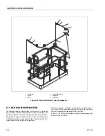
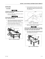
4.20 USE AND CARE OF FALL ARREST SYSTEM
The external fall arrest system is designed to provide a lanyard
attach point while allowing the operator to access areas of an
aircraft for inspection and maintenance purposes. Exit/Enter
the platform through the gate area only. The system is
designed for use by one person.
Personnel must use fall protection at all times. A full body har-
ness and shock absorbing lanyard, not to exceed 6 feet (1.8 m)
in length, is required when using the external fall arrest sys-
tem.
DO NOT OPERATE ANY MACHINE FUNCTIONS WHILE OUTSIDE OF THE PLAT-
FORM. BE CAREFUL WHEN ENTERING/EXITING THE PLATFORM AT ELEVATION.
THE EXTERNAL FALL ARREST SYSTEM REQUIRES AN ANNUAL INSPECTION AND
CERTIFICATION. THE ANNUAL INSPECTION AND CERTIFICATION MUST BE PER-
FORMED BY A COMPETENT PERSON.
If inspection services are required, contact:
Flexible Lifeline Systems
14325 West Hardy Rd.
Houston, TX 77060
Phone: 281-448-8821
IF THE FALL ARREST SYSTEM IS USED TO ARREST A FALL OR IS OTHERWISE
DAMAGED, THE ENTIRE SYSTEM MUST BE REPLACED AND THE PLATFORM
FULLY INSPECTED. REFER TO THE SERVICE MANUAL.
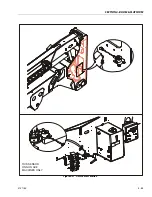
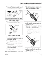
Prior to Use Inspection
Fall arrest systems must be inspected prior to each use.
Replace if there are any signs of wear or damage to any of the
components.
Prior to use inspection should include a visual inspection of
the following items:
Cable: Proper tension, broken strands, corrosion.
Fittings: Loose fittings and fractures, damage to
hanger.
Transfastener: Damage, free and proper sliding
Attaching Hardware: Loose, missing, properly
tightened.
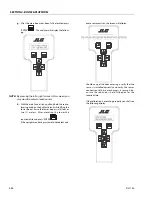
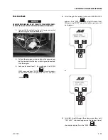
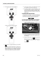
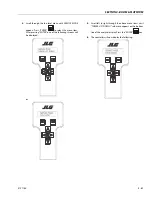
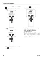
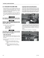
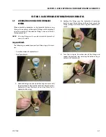
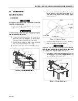
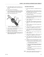
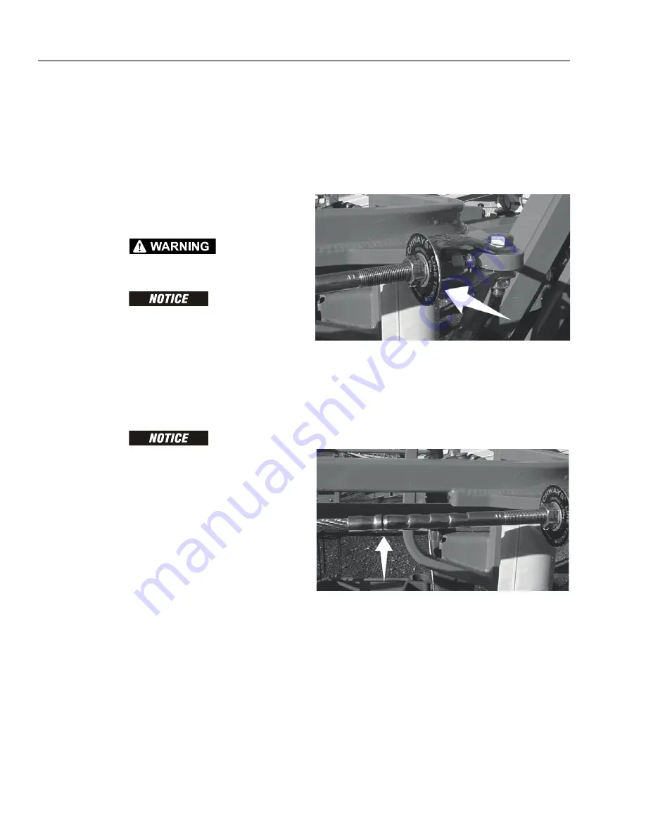
Inspecting Cable Tension and Slip Indicator
Cable tension is adjusted using the Line Tenser. The Line
Tenser is the disc at the end of the cable (shown below). When
proper tension is achieved, the disc will spin by hand. When
less than proper tension is present the disc will not turn by
hand. The cable will stretch normally over time. To tension the
cable, rotate the turnbuckle until proper tension is achieved.
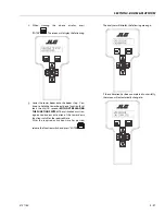
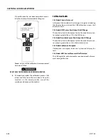
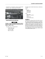
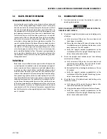
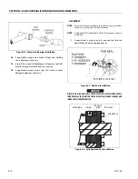
The slip indicator is the short tube crimped beside the end
connection of the cable. If the cable slips from the end con-
nection a gap will be present between the slip indicator and
the end connection. No gap is acceptable. A cable that is
slipped should be taken out of service and the system
replaced.
Shown below is the slip indicator as it should appear.
Содержание 740AJ
Страница 1: ...Service and Maintenance Manual Model 740AJ Prior to S N 0300185827 P N 3121160 October 24 2017 AS NZS...
Страница 2: ......
Страница 51: ...SECTION 2 GENERAL 3121160 2 11 Figure 2 2 Engine Operating Temperature Specifications Ford 4150548 E...
Страница 55: ...SECTION 3 CHASSIS TURNTABLE 3121160 3 3 This page left blank intentionally...
Страница 56: ...SECTION 3 CHASSIS TURNTABLE 3 4 3121160 1 Figure 3 2 Axle and Steering Installation Sheet 1 of 2 0258286 C...
Страница 100: ...SECTION 3 CHASSIS TURNTABLE 3 48 3121160 Figure 3 37 Swing Bearing Tolerance Boom Placement Sheet 1 of 2...
Страница 101: ...SECTION 3 CHASSIS TURNTABLE 3121160 3 49 Figure 3 38 Swing Bearing Tolerance Boom Placement Sheet 2 of 2...
Страница 116: ...SECTION 3 CHASSIS TURNTABLE 3 64 3121160 Figure 3 44 Swing Hub Prior to SN 0300074383...
Страница 124: ...SECTION 3 CHASSIS TURNTABLE 3 72 3121160 Figure 3 45 Swing Drive Hub Fairfield SN 0300074383 through 0300134352...
Страница 180: ...SECTION 3 CHASSIS TURNTABLE 3 128 3121160 1 Figure 3 66 Auxiliary Pump Location 1 AuxiliaryPump 2 HydraulicTank...
Страница 203: ...SECTION 3 CHASSIS TURNTABLE 3121160 3 151 Figure 3 77 EFI Component Location...
Страница 206: ...SECTION 3 CHASSIS TURNTABLE 3 154 3121160 Figure 3 78 ECM EPM Identification ECM EPM...
Страница 213: ...SECTION 3 CHASSIS TURNTABLE 3121160 3 161 Megajector Regulator LockoffSolenoid Figure 3 80 LPG System Components Mixer...
Страница 219: ...SECTION 3 CHASSIS TURNTABLE 3121160 3 167 Figure 3 81 Check Out and Initial Start Up Procedures...
Страница 224: ...SECTION 3 CHASSIS TURNTABLE 3 172 3121160 Figure 3 83 Deutz EMR 2 Troubleshooting Flow Chart...
Страница 225: ...SECTION 3 CHASSIS TURNTABLE 3121160 3 173 Figure 3 84 Deutz EMR 2 Vehicle Side Connection Diagram...
Страница 226: ...SECTION 3 CHASSIS TURNTABLE 3 174 3121160 Figure 3 85 Deutz EMR 2 Engine Side Connection Diagram Sheet 1 of 2...
Страница 227: ...SECTION 3 CHASSIS TURNTABLE 3121160 3 175 Figure 3 86 Deutz EMR 2 Engine Side Connection Diagram Sheet 2 of 2...
Страница 228: ...SECTION 3 CHASSIS TURNTABLE 3 176 3121160 Figure 3 87 EMR 2 Engine Plug Pin Identification...
Страница 229: ...SECTION 3 CHASSIS TURNTABLE 3121160 3 177 Figure 3 88 EMR 2 Vehicle Plug Pin Identification...
Страница 230: ...SECTION 3 CHASSIS TURNTABLE 3 178 3121160 Figure 3 89 EMR2 Fault Codes Sheet 1 of 5...
Страница 231: ...SECTION 3 CHASSIS TURNTABLE 3121160 3 179 Figure 3 90 EMR2 Fault Codes Sheet 2 of 5...
Страница 232: ...SECTION 3 CHASSIS TURNTABLE 3 180 3121160 Figure 3 91 EMR2 Fault Codes Sheet 3 of 5...
Страница 233: ...SECTION 3 CHASSIS TURNTABLE 3121160 3 181 Figure 3 92 EMR2 Fault Codes Sheet 4 of 5...
Страница 234: ...SECTION 3 CHASSIS TURNTABLE 3 182 3121160 Figure 3 93 EMR2 Fault Codes Sheet 5 of 5...
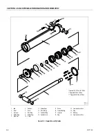
Страница 303: ...SECTION 4 BOOM PLATFORM 3121160 4 31 Figure 4 20 Rotator Assembly HELAC...
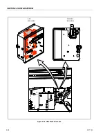
Страница 335: ...SECTION 4 BOOM PLATFORM 3121160 4 63 THIS SENSOR ON NON ADE MACHINES ONLY Figure 4 27 UMS Sensor Location...
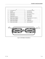
Страница 336: ...SECTION 4 BOOM PLATFORM 4 64 3121160 Figure 4 28 UMS Module Location ADE MACHINES NON ADE MACHINES...
Страница 425: ...SECTION 5 BASIC HYDRAULIC INFORMATION AND SCHEMATICS 3121160 5 81 Figure 5 131 Variable Displacement Pump Rexroth...
Страница 443: ...SECTION 5 BASIC HYDRAULIC INFORMATION AND SCHEMATICS 3121160 5 99 Figure 5 146 Fault Logic Troubleshooting...
Страница 444: ...SECTION 5 BASIC HYDRAULIC INFORMATION AND SCHEMATICS 5 100 3121160 Figure 5 147 Fault Logic Troubleshooting...
Страница 445: ...SECTION 5 BASIC HYDRAULIC INFORMATION AND SCHEMATICS 3121160 5 101 Figure 5 148 Fault Logic Troubleshooting...
Страница 460: ...SECTION 5 BASIC HYDRAULIC INFORMATION AND SCHEMATICS 5 116 3121160 NOTES...
Страница 467: ...SECTION 6 JLG CONTROL SYSTEM 3121160 6 7 Figure 6 2 ADE Block Diagram...
Страница 471: ...SECTION 6 JLG CONTROL SYSTEM 3121160 6 11 Figure 6 6 Analyzer Flow Chart Prior to Version 5 X Software Sheet 4 of 4...
Страница 473: ...SECTION 6 JLG CONTROL SYSTEM 3121160 6 13 Figure 6 8 Analyzer Flow Chart Version 5 X Software Sheet 2 of 4...
Страница 534: ...SECTION 6 JLG CONTROL SYSTEM 6 74 3121160 NOTES...
Страница 545: ...SECTION 7 BASIC ELECTRICAL INFORMATION SCHEMATICS 3121160 7 11 Figure 7 15 Connector Installation...
Страница 580: ...SECTION 7 BASIC ELECTRICAL INFORMATION SCHEMATICS 7 46 3121160 NOTES...
Страница 581: ......


