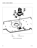
SECTION 3 - CHASSIS & TURNTABLE
3-50
3121160
Wear Tolerance
1.
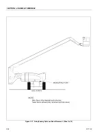
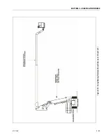
From the underside of the machine, at rear center, with
the main boom fully elevated and fully retracted, and
tower boom stowed, as shown in Figure 3-37., Swing
Bearing Tolerance Boom Placement - (Sheet 1 of 2),
using a magnetic base dial indicator, measure and
record the distance between the swing bearing and
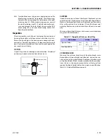
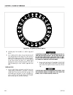
turntable. See Figure 3-40., Swing Bearing Tolerance
Measuring Point.
2.
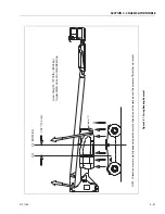
At the same point, with the main boom at horizontal
and fully extended, and the tower boom fully elevated
and fully retracted as shown in Figure 3-38., Swing Bear-
ing Tolerance Boom Placement - (Sheet 2 of 2). Using a
magnetic base dial indicator, measure and record the
distance between the swing bearing and turntable. See
Figure 3-40., Swing Bearing Tolerance Measuring Point.
3.
If a difference greater than 0.079 in. (2.00 mm) is deter-
mined, the swing bearing should be replaced.
4.
If a difference less than 0.079 in. (2.00 mm) is deter-
mined, and any of the following conditions exist, the
bearing should be removed, disassembled, and
inspected for the following:
a.
Metal particles in the grease.
b.
Increased drive power required.
c.
Noise.
d.
Rough rotation.
5.
If bearing inspection shows no defects, reassemble and
return to service.
Swing Bearing Replacement
REMOVAL
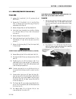
1.
From Ground Control station, operate the boom ade-
quately to provide access to frame opening to rotary
coupling.
NEVER WORK BENEATH THE BOOM WITHOUT FIRST ENGAGING BOOM SAFETY
PROP OR PROVIDING ADEQUATE OVERHEAD SLING SUPPORT AND/OR BLOCK-
ING.
2.
Attach an adequate support sling to the boom and draw
all slack from sling. Prop or block the boom if feasible.
3.
From inside turntable, remove mounting hardware
which attach rotary coupling retaining yoke brackets to
turntable.
HYDRAULIC LINES AND PORTS SHOULD BE CAPPED IMMEDIATELY AFTER DIS-
CONNECTING LINES TO AVOID THE ENTRY OF CONTAMINANTS INTO THE SYS-
TEM.
4.
Tag and disconnect the hydraulic lines from the fittings
on the top of the rotary coupling. Use a suitable con-
tainer to retain any residual hydraulic fluid. Immediately
cap lines and ports.
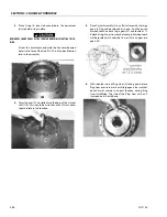
5.
Attach suitable overhead lifting equipment to the base
of the turntable weldment.
6.
Use a suitable tool to scribe a line on the inner race of
the swing bearing and on the underside of the turnta-
ble. This will aid in aligning the bearing upon installa-
tion. Remove the bolts and washers which attach the
turntable to the bearing inner race. Discard the bolts.
7.
Use the lifting equipment to carefully lift the complete
turntable assembly from the bearing. Ensure that no
damage occurs to the turntable, bearing or frame-
mounted components.
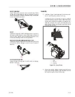
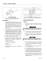
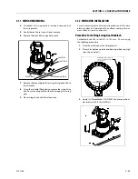
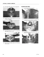
Figure 3-39. Swing Bolt Feeler Gauge Check.
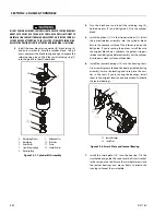
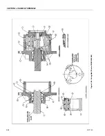
Figure 3-40. Swing Bearing Tolerance Measuring Point.
Содержание 740AJ
Страница 1: ...Service and Maintenance Manual Model 740AJ Prior to S N 0300185827 P N 3121160 October 24 2017 AS NZS...
Страница 2: ......
Страница 51: ...SECTION 2 GENERAL 3121160 2 11 Figure 2 2 Engine Operating Temperature Specifications Ford 4150548 E...
Страница 55: ...SECTION 3 CHASSIS TURNTABLE 3121160 3 3 This page left blank intentionally...
Страница 56: ...SECTION 3 CHASSIS TURNTABLE 3 4 3121160 1 Figure 3 2 Axle and Steering Installation Sheet 1 of 2 0258286 C...
Страница 100: ...SECTION 3 CHASSIS TURNTABLE 3 48 3121160 Figure 3 37 Swing Bearing Tolerance Boom Placement Sheet 1 of 2...
Страница 101: ...SECTION 3 CHASSIS TURNTABLE 3121160 3 49 Figure 3 38 Swing Bearing Tolerance Boom Placement Sheet 2 of 2...
Страница 116: ...SECTION 3 CHASSIS TURNTABLE 3 64 3121160 Figure 3 44 Swing Hub Prior to SN 0300074383...
Страница 124: ...SECTION 3 CHASSIS TURNTABLE 3 72 3121160 Figure 3 45 Swing Drive Hub Fairfield SN 0300074383 through 0300134352...
Страница 180: ...SECTION 3 CHASSIS TURNTABLE 3 128 3121160 1 Figure 3 66 Auxiliary Pump Location 1 AuxiliaryPump 2 HydraulicTank...
Страница 203: ...SECTION 3 CHASSIS TURNTABLE 3121160 3 151 Figure 3 77 EFI Component Location...
Страница 206: ...SECTION 3 CHASSIS TURNTABLE 3 154 3121160 Figure 3 78 ECM EPM Identification ECM EPM...
Страница 213: ...SECTION 3 CHASSIS TURNTABLE 3121160 3 161 Megajector Regulator LockoffSolenoid Figure 3 80 LPG System Components Mixer...
Страница 219: ...SECTION 3 CHASSIS TURNTABLE 3121160 3 167 Figure 3 81 Check Out and Initial Start Up Procedures...
Страница 224: ...SECTION 3 CHASSIS TURNTABLE 3 172 3121160 Figure 3 83 Deutz EMR 2 Troubleshooting Flow Chart...
Страница 225: ...SECTION 3 CHASSIS TURNTABLE 3121160 3 173 Figure 3 84 Deutz EMR 2 Vehicle Side Connection Diagram...
Страница 226: ...SECTION 3 CHASSIS TURNTABLE 3 174 3121160 Figure 3 85 Deutz EMR 2 Engine Side Connection Diagram Sheet 1 of 2...
Страница 227: ...SECTION 3 CHASSIS TURNTABLE 3121160 3 175 Figure 3 86 Deutz EMR 2 Engine Side Connection Diagram Sheet 2 of 2...
Страница 228: ...SECTION 3 CHASSIS TURNTABLE 3 176 3121160 Figure 3 87 EMR 2 Engine Plug Pin Identification...
Страница 229: ...SECTION 3 CHASSIS TURNTABLE 3121160 3 177 Figure 3 88 EMR 2 Vehicle Plug Pin Identification...
Страница 230: ...SECTION 3 CHASSIS TURNTABLE 3 178 3121160 Figure 3 89 EMR2 Fault Codes Sheet 1 of 5...
Страница 231: ...SECTION 3 CHASSIS TURNTABLE 3121160 3 179 Figure 3 90 EMR2 Fault Codes Sheet 2 of 5...
Страница 232: ...SECTION 3 CHASSIS TURNTABLE 3 180 3121160 Figure 3 91 EMR2 Fault Codes Sheet 3 of 5...
Страница 233: ...SECTION 3 CHASSIS TURNTABLE 3121160 3 181 Figure 3 92 EMR2 Fault Codes Sheet 4 of 5...
Страница 234: ...SECTION 3 CHASSIS TURNTABLE 3 182 3121160 Figure 3 93 EMR2 Fault Codes Sheet 5 of 5...
Страница 303: ...SECTION 4 BOOM PLATFORM 3121160 4 31 Figure 4 20 Rotator Assembly HELAC...
Страница 335: ...SECTION 4 BOOM PLATFORM 3121160 4 63 THIS SENSOR ON NON ADE MACHINES ONLY Figure 4 27 UMS Sensor Location...
Страница 336: ...SECTION 4 BOOM PLATFORM 4 64 3121160 Figure 4 28 UMS Module Location ADE MACHINES NON ADE MACHINES...
Страница 425: ...SECTION 5 BASIC HYDRAULIC INFORMATION AND SCHEMATICS 3121160 5 81 Figure 5 131 Variable Displacement Pump Rexroth...
Страница 443: ...SECTION 5 BASIC HYDRAULIC INFORMATION AND SCHEMATICS 3121160 5 99 Figure 5 146 Fault Logic Troubleshooting...
Страница 444: ...SECTION 5 BASIC HYDRAULIC INFORMATION AND SCHEMATICS 5 100 3121160 Figure 5 147 Fault Logic Troubleshooting...
Страница 445: ...SECTION 5 BASIC HYDRAULIC INFORMATION AND SCHEMATICS 3121160 5 101 Figure 5 148 Fault Logic Troubleshooting...
Страница 460: ...SECTION 5 BASIC HYDRAULIC INFORMATION AND SCHEMATICS 5 116 3121160 NOTES...
Страница 467: ...SECTION 6 JLG CONTROL SYSTEM 3121160 6 7 Figure 6 2 ADE Block Diagram...
Страница 471: ...SECTION 6 JLG CONTROL SYSTEM 3121160 6 11 Figure 6 6 Analyzer Flow Chart Prior to Version 5 X Software Sheet 4 of 4...
Страница 473: ...SECTION 6 JLG CONTROL SYSTEM 3121160 6 13 Figure 6 8 Analyzer Flow Chart Version 5 X Software Sheet 2 of 4...
Страница 534: ...SECTION 6 JLG CONTROL SYSTEM 6 74 3121160 NOTES...
Страница 545: ...SECTION 7 BASIC ELECTRICAL INFORMATION SCHEMATICS 3121160 7 11 Figure 7 15 Connector Installation...
Страница 580: ...SECTION 7 BASIC ELECTRICAL INFORMATION SCHEMATICS 7 46 3121160 NOTES...
Страница 581: ......

