SECTION 3 - CHASSIS & TURNTABLE
3121160
3-189
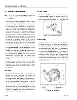
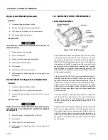
Heated Exhaust Gas Oxygen Sensor
There are two Heated Exhaust Gas Oxygen Sensors (HEGO).
The first HEGO is mounted in the exhaust system downstream
of the engine. It is used to measure the amount of oxygen
present in the exhaust stream and communicate that to the
ECM via an electrical signal. The amount of oxygen present in
the exhaust stream indicates whether the fuel/air ratio is too
rich or too lean. If the HEGO sensor signal indicates that the
exhaust stream is too rich the ECM will decrease or lean the
fuel mixture during engine operation, if the mixture is too lean
the ECM will richen the mixture. The ECM continuously moni-
tors the HEGO sensor output. If a rich or lean condition is pres-
ent for an extended period of time, and the ECM cannot
correct the condition, the ECM will set a diagnostic code and
turn on the MIL light in control box.
The second HEGO is mounted in the exhaust system after the
muffler. It measures the amount of oxygen in the exhaust sys-
tem after the catalyst treatment has been completed in the
muffler. If the ECM detects that the catalytic action in the muf-
fler is not sufficient and fuel correction cannot correct the mal-
function the MIL light is illuminated in the control box and a
DTC code will stored in the computer.
THE HEATED EXHAUST GAS OXYGEN SENSOR IS AN EMISSION CONTROL
DEVICE. IF THE HEGO FAILS TO OPERATE, REPLACE IT WITH AN OEM REPLACE-
MENT PART. THE HEGO SENSOR IS SENSITIVE TO SILICONE OR SILICONE
BASED PRODUCTS AND CAN BECOME CONTAMINATED. AVOID USING SILICONE
SEALERS OR HOSES TREATED WITH SILICONE LUBRICANTS IN THE AIR
STREAM OR FUEL LINES.
Gasoline Multi Point Fuel Injection System (MPFI)
The primary components of the Gasoline Multi Point Fuel
Injection (MPFI) fuel system are the fuel tank, electric fuel
pump, fuel pressure and temperature sensor manifold, fuel fil-
ter and fuel rail.
Gasoline Fuel Pump
The Gasoline is stored as a liquid in the fuel tank and in drawn
into the fuel system by an electric fuel pump. The fuel pump
will receive a signal from the ECM to prime the fuel system for
approximately 2 seconds prior to start. Priming of the fuel sys-
tem provides for a quicker start, when the engine begins to
crank.
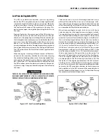
Gasoline Pressure And Temperature Sensor
Manifold
This engine is equipped with a fuel injector rail that does not
have a pressure regulator or a return circuit to the fuel tank.
Fuel pressure for this engine is regulated by the engine’s ECM.
The ECM receive fuel pressure and temperature feedback from
the gasoline fuel sensor manifold and uses this information to
control the ground side of the fuel pump. Fuel pressure is reg-
ulated by the ECM pulse width modulating (PWM) the fuel
pump. The fuel pressure and temperature sensor manifold has
a return or "bleed" circuit that connects back to the fuel tank.
This circuit is used to bleed off any vapor that develops in the
line and return a small amount of fuel to the tank. The fuel
comes from the fuel tank and passes through the fuel pump.
Fuel exits the fuel pump, passes through the filter and then
enters the fuel pressure and temperature manifold assembly.
Fuel flows through the feed circuit and is delivered to the fuel
injector rail. Fuel that enters the bleed circuits through they
bypass valve in the manifold is returned to the fuel tank.
Figure 3-102. Heated Exhaust Gas Oxygen Sensor
Figure 3-103. Gasoline Fuel Pressure and Temperature
Manifold Assembly
Содержание 740AJ
Страница 1: ...Service and Maintenance Manual Model 740AJ Prior to S N 0300185827 P N 3121160 October 24 2017 AS NZS...
Страница 2: ......
Страница 51: ...SECTION 2 GENERAL 3121160 2 11 Figure 2 2 Engine Operating Temperature Specifications Ford 4150548 E...
Страница 55: ...SECTION 3 CHASSIS TURNTABLE 3121160 3 3 This page left blank intentionally...
Страница 56: ...SECTION 3 CHASSIS TURNTABLE 3 4 3121160 1 Figure 3 2 Axle and Steering Installation Sheet 1 of 2 0258286 C...
Страница 100: ...SECTION 3 CHASSIS TURNTABLE 3 48 3121160 Figure 3 37 Swing Bearing Tolerance Boom Placement Sheet 1 of 2...
Страница 101: ...SECTION 3 CHASSIS TURNTABLE 3121160 3 49 Figure 3 38 Swing Bearing Tolerance Boom Placement Sheet 2 of 2...
Страница 116: ...SECTION 3 CHASSIS TURNTABLE 3 64 3121160 Figure 3 44 Swing Hub Prior to SN 0300074383...
Страница 124: ...SECTION 3 CHASSIS TURNTABLE 3 72 3121160 Figure 3 45 Swing Drive Hub Fairfield SN 0300074383 through 0300134352...
Страница 180: ...SECTION 3 CHASSIS TURNTABLE 3 128 3121160 1 Figure 3 66 Auxiliary Pump Location 1 AuxiliaryPump 2 HydraulicTank...
Страница 203: ...SECTION 3 CHASSIS TURNTABLE 3121160 3 151 Figure 3 77 EFI Component Location...
Страница 206: ...SECTION 3 CHASSIS TURNTABLE 3 154 3121160 Figure 3 78 ECM EPM Identification ECM EPM...
Страница 213: ...SECTION 3 CHASSIS TURNTABLE 3121160 3 161 Megajector Regulator LockoffSolenoid Figure 3 80 LPG System Components Mixer...
Страница 219: ...SECTION 3 CHASSIS TURNTABLE 3121160 3 167 Figure 3 81 Check Out and Initial Start Up Procedures...
Страница 224: ...SECTION 3 CHASSIS TURNTABLE 3 172 3121160 Figure 3 83 Deutz EMR 2 Troubleshooting Flow Chart...
Страница 225: ...SECTION 3 CHASSIS TURNTABLE 3121160 3 173 Figure 3 84 Deutz EMR 2 Vehicle Side Connection Diagram...
Страница 226: ...SECTION 3 CHASSIS TURNTABLE 3 174 3121160 Figure 3 85 Deutz EMR 2 Engine Side Connection Diagram Sheet 1 of 2...
Страница 227: ...SECTION 3 CHASSIS TURNTABLE 3121160 3 175 Figure 3 86 Deutz EMR 2 Engine Side Connection Diagram Sheet 2 of 2...
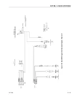
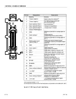
Страница 228: ...SECTION 3 CHASSIS TURNTABLE 3 176 3121160 Figure 3 87 EMR 2 Engine Plug Pin Identification...
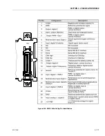
Страница 229: ...SECTION 3 CHASSIS TURNTABLE 3121160 3 177 Figure 3 88 EMR 2 Vehicle Plug Pin Identification...
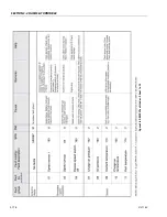
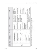
Страница 230: ...SECTION 3 CHASSIS TURNTABLE 3 178 3121160 Figure 3 89 EMR2 Fault Codes Sheet 1 of 5...
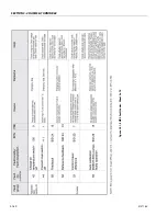
Страница 231: ...SECTION 3 CHASSIS TURNTABLE 3121160 3 179 Figure 3 90 EMR2 Fault Codes Sheet 2 of 5...
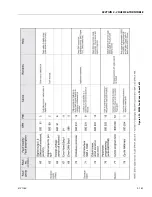
Страница 232: ...SECTION 3 CHASSIS TURNTABLE 3 180 3121160 Figure 3 91 EMR2 Fault Codes Sheet 3 of 5...
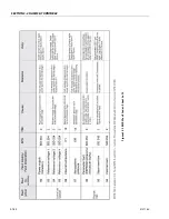
Страница 233: ...SECTION 3 CHASSIS TURNTABLE 3121160 3 181 Figure 3 92 EMR2 Fault Codes Sheet 4 of 5...
Страница 234: ...SECTION 3 CHASSIS TURNTABLE 3 182 3121160 Figure 3 93 EMR2 Fault Codes Sheet 5 of 5...
Страница 303: ...SECTION 4 BOOM PLATFORM 3121160 4 31 Figure 4 20 Rotator Assembly HELAC...
Страница 335: ...SECTION 4 BOOM PLATFORM 3121160 4 63 THIS SENSOR ON NON ADE MACHINES ONLY Figure 4 27 UMS Sensor Location...
Страница 336: ...SECTION 4 BOOM PLATFORM 4 64 3121160 Figure 4 28 UMS Module Location ADE MACHINES NON ADE MACHINES...
Страница 425: ...SECTION 5 BASIC HYDRAULIC INFORMATION AND SCHEMATICS 3121160 5 81 Figure 5 131 Variable Displacement Pump Rexroth...
Страница 443: ...SECTION 5 BASIC HYDRAULIC INFORMATION AND SCHEMATICS 3121160 5 99 Figure 5 146 Fault Logic Troubleshooting...
Страница 444: ...SECTION 5 BASIC HYDRAULIC INFORMATION AND SCHEMATICS 5 100 3121160 Figure 5 147 Fault Logic Troubleshooting...
Страница 445: ...SECTION 5 BASIC HYDRAULIC INFORMATION AND SCHEMATICS 3121160 5 101 Figure 5 148 Fault Logic Troubleshooting...
Страница 460: ...SECTION 5 BASIC HYDRAULIC INFORMATION AND SCHEMATICS 5 116 3121160 NOTES...
Страница 467: ...SECTION 6 JLG CONTROL SYSTEM 3121160 6 7 Figure 6 2 ADE Block Diagram...
Страница 471: ...SECTION 6 JLG CONTROL SYSTEM 3121160 6 11 Figure 6 6 Analyzer Flow Chart Prior to Version 5 X Software Sheet 4 of 4...
Страница 473: ...SECTION 6 JLG CONTROL SYSTEM 3121160 6 13 Figure 6 8 Analyzer Flow Chart Version 5 X Software Sheet 2 of 4...
Страница 534: ...SECTION 6 JLG CONTROL SYSTEM 6 74 3121160 NOTES...
Страница 545: ...SECTION 7 BASIC ELECTRICAL INFORMATION SCHEMATICS 3121160 7 11 Figure 7 15 Connector Installation...
Страница 580: ...SECTION 7 BASIC ELECTRICAL INFORMATION SCHEMATICS 7 46 3121160 NOTES...
Страница 581: ......

