SECTION 3 - CHASSIS & TURNTABLE
3-202
3121160
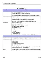
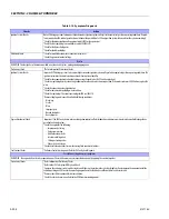
Exhaust System Checks
² Check the exhaust system for a possible restriction:
- Inspect the exhaust system for damaged or collapsed pipes
- Inspect the muffler for signs of heat distress or for possible internal failure.
² Check for possible plugged catalytic converter. Refer to Restricted Exhaust System Diagnosis
Hard Start
DEFINITION: The engine cranks OK, but does not start for a long time. The engine does eventually run, or may start but immediately dies.
Preliminary Checks
² Refer to Important Preliminary Checks.
² Make sure the vehicle's operator is using the correct starting procedure.
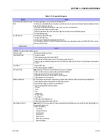
Sensor Checks
²Check the Engine Coolant Temperature sensor with the scan tool. Compare the engine coolant temperature with the ambient air temperature
on a cold engine. IF the coolant temperature reading is more than 5 degrees greater or less than the ambient air temperature on a cold engine,
check for high resistance in the coolant sensor circuit. Refer to DTC 111
² Check the Crankshaft Position (CKP) sensor.
²Check the Throttle position (TPS) sensor.
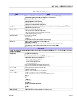
Fuel System Checks
Important: A closed LPG manual fuel shut off valve will create an extended crank OR no start condition.
² Verify the excess flow valve in the LPG manual shut-off valve is not tripped.
² Check mixer module assembly for proper installation and leakage.
² Verify proper operation of the low pressure lock-off solenoids.
² Verify proper operation of the EPR
² Check for air intake system leakage between the mixer and the throttle body.
² Check the fuel system pressures. Refer to the Fuel System Diagnosis.
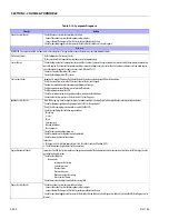
Ignition System Checks
Note: LPG being a gaseous fuel requires higher secondary ignition system voltages for the equivalent gasoline operating conditions.
² Check for the proper ignition voltage output with J 26792 or the equivalent.
² Verify that the spark plugs are correct for use with LPG (R42LTS)
² Check the spark plugs for the following conditions:
- Wet plugs
- Cracks
- Wear
- Improper gap
- Burned electrodes
- Heavy deposits
² Check for bare or shorted ignition wires.
² Check for moisture in the distributor cap if applicable.
² Check for loose ignition coil connections.
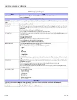
Important:
1. If the engine starts but then immediately stalls, Check the Crankshaft Position (CKP).
2. Check for improper gap, debris or faulty connections.
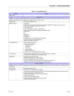
Engine Mechanical Checks
Important: The LPG Fuel system works on a fumigation principle of fuel introduction and is more sensitive to intake manifold leakage than the
gasoline fuel supply system.
² Check for the following:
- Vacuum leaks
- Improper valve timing
- Low compression
- Bent pushrods
- Worn rocker arms
- Broken or weak valve springs
- Worn camshaft lobes.
² Check the intake and exhaust manifolds for casting flash.
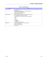
Exhaust System Checks
² Check the exhaust system for a possible restriction:
- Inspect the exhaust system for damaged or collapsed pipes
- Inspect the muffler for signs of heat distress or for possible internal failure.
² Check for possible plugged catalytic converter. Refer to Restricted Exhaust System Diagnosis or Exhaust System in the GM Base Engine Service
Manual
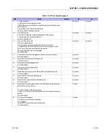
Table 3-15. Symptom Diagnosis
Checks
Action
Содержание 740AJ
Страница 1: ...Service and Maintenance Manual Model 740AJ Prior to S N 0300185827 P N 3121160 October 24 2017 AS NZS...
Страница 2: ......
Страница 51: ...SECTION 2 GENERAL 3121160 2 11 Figure 2 2 Engine Operating Temperature Specifications Ford 4150548 E...
Страница 55: ...SECTION 3 CHASSIS TURNTABLE 3121160 3 3 This page left blank intentionally...
Страница 56: ...SECTION 3 CHASSIS TURNTABLE 3 4 3121160 1 Figure 3 2 Axle and Steering Installation Sheet 1 of 2 0258286 C...
Страница 100: ...SECTION 3 CHASSIS TURNTABLE 3 48 3121160 Figure 3 37 Swing Bearing Tolerance Boom Placement Sheet 1 of 2...
Страница 101: ...SECTION 3 CHASSIS TURNTABLE 3121160 3 49 Figure 3 38 Swing Bearing Tolerance Boom Placement Sheet 2 of 2...
Страница 116: ...SECTION 3 CHASSIS TURNTABLE 3 64 3121160 Figure 3 44 Swing Hub Prior to SN 0300074383...
Страница 124: ...SECTION 3 CHASSIS TURNTABLE 3 72 3121160 Figure 3 45 Swing Drive Hub Fairfield SN 0300074383 through 0300134352...
Страница 180: ...SECTION 3 CHASSIS TURNTABLE 3 128 3121160 1 Figure 3 66 Auxiliary Pump Location 1 AuxiliaryPump 2 HydraulicTank...
Страница 203: ...SECTION 3 CHASSIS TURNTABLE 3121160 3 151 Figure 3 77 EFI Component Location...
Страница 206: ...SECTION 3 CHASSIS TURNTABLE 3 154 3121160 Figure 3 78 ECM EPM Identification ECM EPM...
Страница 213: ...SECTION 3 CHASSIS TURNTABLE 3121160 3 161 Megajector Regulator LockoffSolenoid Figure 3 80 LPG System Components Mixer...
Страница 219: ...SECTION 3 CHASSIS TURNTABLE 3121160 3 167 Figure 3 81 Check Out and Initial Start Up Procedures...
Страница 224: ...SECTION 3 CHASSIS TURNTABLE 3 172 3121160 Figure 3 83 Deutz EMR 2 Troubleshooting Flow Chart...
Страница 225: ...SECTION 3 CHASSIS TURNTABLE 3121160 3 173 Figure 3 84 Deutz EMR 2 Vehicle Side Connection Diagram...
Страница 226: ...SECTION 3 CHASSIS TURNTABLE 3 174 3121160 Figure 3 85 Deutz EMR 2 Engine Side Connection Diagram Sheet 1 of 2...
Страница 227: ...SECTION 3 CHASSIS TURNTABLE 3121160 3 175 Figure 3 86 Deutz EMR 2 Engine Side Connection Diagram Sheet 2 of 2...
Страница 228: ...SECTION 3 CHASSIS TURNTABLE 3 176 3121160 Figure 3 87 EMR 2 Engine Plug Pin Identification...
Страница 229: ...SECTION 3 CHASSIS TURNTABLE 3121160 3 177 Figure 3 88 EMR 2 Vehicle Plug Pin Identification...
Страница 230: ...SECTION 3 CHASSIS TURNTABLE 3 178 3121160 Figure 3 89 EMR2 Fault Codes Sheet 1 of 5...
Страница 231: ...SECTION 3 CHASSIS TURNTABLE 3121160 3 179 Figure 3 90 EMR2 Fault Codes Sheet 2 of 5...
Страница 232: ...SECTION 3 CHASSIS TURNTABLE 3 180 3121160 Figure 3 91 EMR2 Fault Codes Sheet 3 of 5...
Страница 233: ...SECTION 3 CHASSIS TURNTABLE 3121160 3 181 Figure 3 92 EMR2 Fault Codes Sheet 4 of 5...
Страница 234: ...SECTION 3 CHASSIS TURNTABLE 3 182 3121160 Figure 3 93 EMR2 Fault Codes Sheet 5 of 5...
Страница 303: ...SECTION 4 BOOM PLATFORM 3121160 4 31 Figure 4 20 Rotator Assembly HELAC...
Страница 335: ...SECTION 4 BOOM PLATFORM 3121160 4 63 THIS SENSOR ON NON ADE MACHINES ONLY Figure 4 27 UMS Sensor Location...
Страница 336: ...SECTION 4 BOOM PLATFORM 4 64 3121160 Figure 4 28 UMS Module Location ADE MACHINES NON ADE MACHINES...
Страница 425: ...SECTION 5 BASIC HYDRAULIC INFORMATION AND SCHEMATICS 3121160 5 81 Figure 5 131 Variable Displacement Pump Rexroth...
Страница 443: ...SECTION 5 BASIC HYDRAULIC INFORMATION AND SCHEMATICS 3121160 5 99 Figure 5 146 Fault Logic Troubleshooting...
Страница 444: ...SECTION 5 BASIC HYDRAULIC INFORMATION AND SCHEMATICS 5 100 3121160 Figure 5 147 Fault Logic Troubleshooting...
Страница 445: ...SECTION 5 BASIC HYDRAULIC INFORMATION AND SCHEMATICS 3121160 5 101 Figure 5 148 Fault Logic Troubleshooting...
Страница 460: ...SECTION 5 BASIC HYDRAULIC INFORMATION AND SCHEMATICS 5 116 3121160 NOTES...
Страница 467: ...SECTION 6 JLG CONTROL SYSTEM 3121160 6 7 Figure 6 2 ADE Block Diagram...
Страница 471: ...SECTION 6 JLG CONTROL SYSTEM 3121160 6 11 Figure 6 6 Analyzer Flow Chart Prior to Version 5 X Software Sheet 4 of 4...
Страница 473: ...SECTION 6 JLG CONTROL SYSTEM 3121160 6 13 Figure 6 8 Analyzer Flow Chart Version 5 X Software Sheet 2 of 4...
Страница 534: ...SECTION 6 JLG CONTROL SYSTEM 6 74 3121160 NOTES...
Страница 545: ...SECTION 7 BASIC ELECTRICAL INFORMATION SCHEMATICS 3121160 7 11 Figure 7 15 Connector Installation...
Страница 580: ...SECTION 7 BASIC ELECTRICAL INFORMATION SCHEMATICS 7 46 3121160 NOTES...
Страница 581: ......

