


SECTION 3 - CHASSIS & TURNTABLE
3121160
3-215
Coalescer (Air/Oil Separator) Replacement
This is a spin-on, throw away type unit. Before attempting to
change ensure all pressure is relieved from the system. Change
in accordance with Maintenance Guidelines. If oil carryover
into the service line occurs and the oil scavenge return line
scavenge shows little or no oil return, then change the ele-
ment. Verify receiver is not over full.
USE ONLY ORIGINAL EQUIPMENT COALESCER ELEMENT TO ENSURE PRESSURE
RATING AND PERFORMANCE IS SATISFACTORY.
REMOVAL:
1.
Remove old element (use strap wrench if required) by
turning anti-clockwise and discard as appropriate and in
accordance with any pertinent regulations.
REPLACEMENT:
1.
Apply a light film of oil to the seal surface on the new
element.
2.
Screw element on clockwise until it seats on the head,
rotate an additional 3/4 turn (by hand). Take care not to
damage element.
3.
Start up and check for leaks.
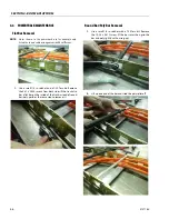
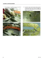
Air Filter Replacement
DO NOT replace with compressor in operation. If environment
is dirty or dusty an earlier change out may be required. To
ensure correct filtration use only original equipment filters.
REMOVAL:
1.
Unscrew the wing nut on top of the air filter and remove
filter cover.
2.
Discard filter as appropriate and in accordance with any
pertinent regulations.
REPLACEMENT:
1.
Clean cover and any dirt inside filter housing taking
extreme care that no dust/dirt particles reach the air
intake of the compressor.
2.
Fit new element inside housing.
3.
Replace lid and tighten wing nut on top of air filter
assembly.
4.
Test run and functional test.
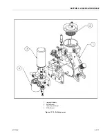
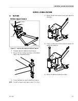
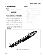
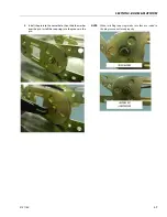
Belts - Tightening and Replacement
Correct tensioning and alignment is important for belt life,
bearing life and power transmission.
Correct tensioning and alignment was provided at time of
shipment from the factory. However, since maximum belt
elongation will occur within the first 50 hours of operation (Of
new belts), their tension should be checked several times dur-
ing this period and corrected as required. The belts should
thereafter be checked periodically in order to obtain maxi-
mum life and performance.
NOTE:
To avoid possible belt damage, never force belts over the
sheaves. Oil spilled or splashed onto the belts in any quan-
tity will cause slippage and severely reduce belt life - take
care when filling compressor oil.
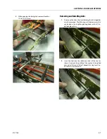
REPLACING/TIGHTENING V-BELTS:
1.
Loosen slightly the bolt at the base of the hydraulic
motor mounting bracket. This will allow the hydraulic
motor to be moved in or out to tighten or loosen the
belts.
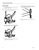
2.
Back off adjusting bolt lock nut. Screw the adjusting bolt
clockwise to tighten belt or anti clockwise to loosen
belts.
3.
After adjustments have been made, tighten base bolt to
insure no further movement.
TENSION DATA
Deflection at center of belt span 0.25 in. (6.35 mm), with a
force of 4 pounds (1.8 kg).
Pulley alignment is set at factory and shouldn’t need to be
adjusted, if it is found necessary to adjust the pulley align-
ment, this
is done by loosening the four bolts that hold down
the base plate to the frame and adjust per following instruc-
tions.
Ensure pulleys are aligned by using a long straight edge which
will span both pulleys. Position the straight edge on the sides
of the pulleys, if they are in-line there should be no gaps
between the straight edge and the pulleys (for the full contact
distance across each pulley side), adjust as necessary to get
correct alignment and tension.
It may be necessary to repeat and check several times before
both tension and alignment are satisfied.
Содержание 740AJ
Страница 1: ...Service and Maintenance Manual Model 740AJ Prior to S N 0300185827 P N 3121160 October 24 2017 AS NZS...
Страница 2: ......
Страница 51: ...SECTION 2 GENERAL 3121160 2 11 Figure 2 2 Engine Operating Temperature Specifications Ford 4150548 E...
Страница 55: ...SECTION 3 CHASSIS TURNTABLE 3121160 3 3 This page left blank intentionally...
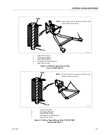
Страница 56: ...SECTION 3 CHASSIS TURNTABLE 3 4 3121160 1 Figure 3 2 Axle and Steering Installation Sheet 1 of 2 0258286 C...
Страница 100: ...SECTION 3 CHASSIS TURNTABLE 3 48 3121160 Figure 3 37 Swing Bearing Tolerance Boom Placement Sheet 1 of 2...
Страница 101: ...SECTION 3 CHASSIS TURNTABLE 3121160 3 49 Figure 3 38 Swing Bearing Tolerance Boom Placement Sheet 2 of 2...
Страница 116: ...SECTION 3 CHASSIS TURNTABLE 3 64 3121160 Figure 3 44 Swing Hub Prior to SN 0300074383...
Страница 124: ...SECTION 3 CHASSIS TURNTABLE 3 72 3121160 Figure 3 45 Swing Drive Hub Fairfield SN 0300074383 through 0300134352...
Страница 180: ...SECTION 3 CHASSIS TURNTABLE 3 128 3121160 1 Figure 3 66 Auxiliary Pump Location 1 AuxiliaryPump 2 HydraulicTank...
Страница 203: ...SECTION 3 CHASSIS TURNTABLE 3121160 3 151 Figure 3 77 EFI Component Location...
Страница 206: ...SECTION 3 CHASSIS TURNTABLE 3 154 3121160 Figure 3 78 ECM EPM Identification ECM EPM...
Страница 213: ...SECTION 3 CHASSIS TURNTABLE 3121160 3 161 Megajector Regulator LockoffSolenoid Figure 3 80 LPG System Components Mixer...
Страница 219: ...SECTION 3 CHASSIS TURNTABLE 3121160 3 167 Figure 3 81 Check Out and Initial Start Up Procedures...
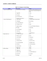
Страница 224: ...SECTION 3 CHASSIS TURNTABLE 3 172 3121160 Figure 3 83 Deutz EMR 2 Troubleshooting Flow Chart...
Страница 225: ...SECTION 3 CHASSIS TURNTABLE 3121160 3 173 Figure 3 84 Deutz EMR 2 Vehicle Side Connection Diagram...
Страница 226: ...SECTION 3 CHASSIS TURNTABLE 3 174 3121160 Figure 3 85 Deutz EMR 2 Engine Side Connection Diagram Sheet 1 of 2...
Страница 227: ...SECTION 3 CHASSIS TURNTABLE 3121160 3 175 Figure 3 86 Deutz EMR 2 Engine Side Connection Diagram Sheet 2 of 2...
Страница 228: ...SECTION 3 CHASSIS TURNTABLE 3 176 3121160 Figure 3 87 EMR 2 Engine Plug Pin Identification...
Страница 229: ...SECTION 3 CHASSIS TURNTABLE 3121160 3 177 Figure 3 88 EMR 2 Vehicle Plug Pin Identification...
Страница 230: ...SECTION 3 CHASSIS TURNTABLE 3 178 3121160 Figure 3 89 EMR2 Fault Codes Sheet 1 of 5...
Страница 231: ...SECTION 3 CHASSIS TURNTABLE 3121160 3 179 Figure 3 90 EMR2 Fault Codes Sheet 2 of 5...
Страница 232: ...SECTION 3 CHASSIS TURNTABLE 3 180 3121160 Figure 3 91 EMR2 Fault Codes Sheet 3 of 5...
Страница 233: ...SECTION 3 CHASSIS TURNTABLE 3121160 3 181 Figure 3 92 EMR2 Fault Codes Sheet 4 of 5...
Страница 234: ...SECTION 3 CHASSIS TURNTABLE 3 182 3121160 Figure 3 93 EMR2 Fault Codes Sheet 5 of 5...
Страница 303: ...SECTION 4 BOOM PLATFORM 3121160 4 31 Figure 4 20 Rotator Assembly HELAC...
Страница 335: ...SECTION 4 BOOM PLATFORM 3121160 4 63 THIS SENSOR ON NON ADE MACHINES ONLY Figure 4 27 UMS Sensor Location...
Страница 336: ...SECTION 4 BOOM PLATFORM 4 64 3121160 Figure 4 28 UMS Module Location ADE MACHINES NON ADE MACHINES...
Страница 425: ...SECTION 5 BASIC HYDRAULIC INFORMATION AND SCHEMATICS 3121160 5 81 Figure 5 131 Variable Displacement Pump Rexroth...
Страница 443: ...SECTION 5 BASIC HYDRAULIC INFORMATION AND SCHEMATICS 3121160 5 99 Figure 5 146 Fault Logic Troubleshooting...
Страница 444: ...SECTION 5 BASIC HYDRAULIC INFORMATION AND SCHEMATICS 5 100 3121160 Figure 5 147 Fault Logic Troubleshooting...
Страница 445: ...SECTION 5 BASIC HYDRAULIC INFORMATION AND SCHEMATICS 3121160 5 101 Figure 5 148 Fault Logic Troubleshooting...
Страница 460: ...SECTION 5 BASIC HYDRAULIC INFORMATION AND SCHEMATICS 5 116 3121160 NOTES...
Страница 467: ...SECTION 6 JLG CONTROL SYSTEM 3121160 6 7 Figure 6 2 ADE Block Diagram...
Страница 471: ...SECTION 6 JLG CONTROL SYSTEM 3121160 6 11 Figure 6 6 Analyzer Flow Chart Prior to Version 5 X Software Sheet 4 of 4...
Страница 473: ...SECTION 6 JLG CONTROL SYSTEM 3121160 6 13 Figure 6 8 Analyzer Flow Chart Version 5 X Software Sheet 2 of 4...
Страница 534: ...SECTION 6 JLG CONTROL SYSTEM 6 74 3121160 NOTES...
Страница 545: ...SECTION 7 BASIC ELECTRICAL INFORMATION SCHEMATICS 3121160 7 11 Figure 7 15 Connector Installation...
Страница 580: ...SECTION 7 BASIC ELECTRICAL INFORMATION SCHEMATICS 7 46 3121160 NOTES...
Страница 581: ......


