SECTION 3 - CHASSIS & TURNTABLE
3-18
3121160
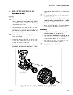
3.6
DRIVE BRAKE - MICO (PRIOR TO SN
0300138447)
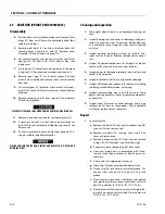
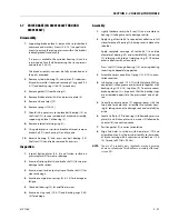
Disassembly
1.
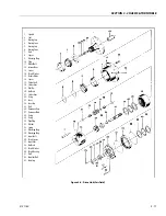
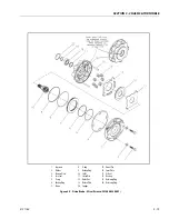
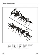
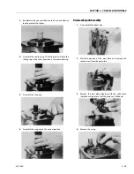
Remove pressure plate (3) from cover plate (16) by
removing capscrews (1) and washers (2).
PRESSURE PLATE IS UNDER SPRING TENSION OF APPROXIMATELY 907 KGF
(2000 IBS). THE TWO CAPSCREWS MUST BE LOOSENED EVENLY TO RELIEVE
THIS FORCE. IF A HYDRAULIC PRESS IS AVAILABLE, 1361 KGF (3000 IBS) MIN-
IMUM, THE PRESSURE PLATE CAN BE HELD IN POSITION WHILE REMOVING
THE CAPSCREWS. COVER PLATE (16) MUST BE SUPPORTED AS SHOWN IN FIG-
URE 3-9.
2.
Remove case seal (4) from cover plate (16).
3.
Remove piston (7) from pressure plate (3).
4.
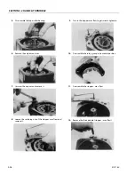
Remove a-ring (5), backup ring (6), a-ring (8) and backup
ring (9) from piston (7).
5.
Remove stator disc (11), rotor disc (12) and return plate
(13) from cover (16).
NOTE:
Not all models use the same number of springs or spring
pattern.
6.
Remove dowel pins (15) and springs (14) from cover
plate (16). Record this information for assembly pur-
poses.
7.
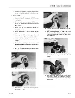
Remove retaining ring (19) from cover plate (16).
8.
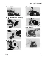
Remove shaft (10) by pressing or using a soft mallet on
male end of shaft (10).
NOTE:
Cover plate (16) must be supported as shown in FIGURE 3-
9.
9.
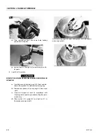
Remove retaining ring (20) from cover plate (16) and
press out oil seal (17) and bearing (18) if required.
NOTE:
Cover plate (16) must be sup¦ported as indicated in Figure
3-9.
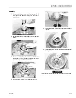
Assembly
LUBRICATE ALL RUBBER COMPONENTS FROM REPAIR KIT WITH CLEAN TYPE
FLUID USED IN THE SYSTEM.
1.
Use an alkaline wash to clean parts before assembly.
2.
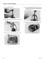
Press oil seal (17) into cover plate (16) until it is flush with
bearing shoulder. Note direction of seal.
3.
Press bearing (18) into position until it bottoms out on
borestep.
NOTE:
Cover plate (16) must be supported as indicated in Figure
3-9.
4.
Install retaining ring (20) in cover plate (16).
5.
Press shaft (10) into bearing (18) until it bottoms on
shoulder.
NOTE:
Bearing (18) inner race and cover plate (16) must be sup-
ported as indicated in Figure 1 during this operation.
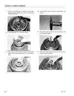
6.
Install retaining ring (19) on shaft (10).
7.
Insert dowel pins (15) and springs (14) in cover plate
(16).
NOTE:
Be sure to use the same number of springs and spring pat-
tern as recorded during disassembly.
8.
Position return plate (13) on springs (14).
NOTE:
Discs (11 & 12) and return plate (13) must remain dry dur-
ing installation. No oil residue must be allowed to contami-
nate disc surfaces.
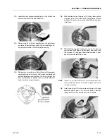
9.
Install rotor disc (12) and stator disc (13).
10.
Install o-ring (5), backup ring (6), o-ring (8) and backup
ring (9) on piston (7). Note order of a-rings and backup
rings. Insert piston (7) into pressure plate (3).
NOTE:
Be careful not to shear o-rings or backup rings. Be careful
not to scratch or mar piston.
11.
Install new case seal (4) in cover plate (16).
12.
Position pressure plate (3) on cover plate (16) aligning
dowel pins (15) with holes in pressure plate.
13.
Install capscrews (1) and washers (2) and tighten evenly
to draw pressure plate (3) to cover plate (16). Torque
capscrews 55 ft. lbs. (74.6 Nm).
NOTE:
A hydraulic press will simplify installation of pressure plate
on cover. Clamp pressure plate in position while tightening
the capscrews. Cover plate (16) must be supported as indi-
cated in Figure 3-9.
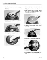
IF HYDROSTATIC BENCH TESTING IS PERFORMED ON THE BRAKE ASSEMBLY,
RELEASE PRESSURE MUST NOT EXCEED 137.9 BAR (2000 PSI).
Содержание 740AJ
Страница 1: ...Service and Maintenance Manual Model 740AJ Prior to S N 0300185827 P N 3121160 October 24 2017 AS NZS...
Страница 2: ......
Страница 51: ...SECTION 2 GENERAL 3121160 2 11 Figure 2 2 Engine Operating Temperature Specifications Ford 4150548 E...
Страница 55: ...SECTION 3 CHASSIS TURNTABLE 3121160 3 3 This page left blank intentionally...
Страница 56: ...SECTION 3 CHASSIS TURNTABLE 3 4 3121160 1 Figure 3 2 Axle and Steering Installation Sheet 1 of 2 0258286 C...
Страница 100: ...SECTION 3 CHASSIS TURNTABLE 3 48 3121160 Figure 3 37 Swing Bearing Tolerance Boom Placement Sheet 1 of 2...
Страница 101: ...SECTION 3 CHASSIS TURNTABLE 3121160 3 49 Figure 3 38 Swing Bearing Tolerance Boom Placement Sheet 2 of 2...
Страница 116: ...SECTION 3 CHASSIS TURNTABLE 3 64 3121160 Figure 3 44 Swing Hub Prior to SN 0300074383...
Страница 124: ...SECTION 3 CHASSIS TURNTABLE 3 72 3121160 Figure 3 45 Swing Drive Hub Fairfield SN 0300074383 through 0300134352...
Страница 180: ...SECTION 3 CHASSIS TURNTABLE 3 128 3121160 1 Figure 3 66 Auxiliary Pump Location 1 AuxiliaryPump 2 HydraulicTank...
Страница 203: ...SECTION 3 CHASSIS TURNTABLE 3121160 3 151 Figure 3 77 EFI Component Location...
Страница 206: ...SECTION 3 CHASSIS TURNTABLE 3 154 3121160 Figure 3 78 ECM EPM Identification ECM EPM...
Страница 213: ...SECTION 3 CHASSIS TURNTABLE 3121160 3 161 Megajector Regulator LockoffSolenoid Figure 3 80 LPG System Components Mixer...
Страница 219: ...SECTION 3 CHASSIS TURNTABLE 3121160 3 167 Figure 3 81 Check Out and Initial Start Up Procedures...
Страница 224: ...SECTION 3 CHASSIS TURNTABLE 3 172 3121160 Figure 3 83 Deutz EMR 2 Troubleshooting Flow Chart...
Страница 225: ...SECTION 3 CHASSIS TURNTABLE 3121160 3 173 Figure 3 84 Deutz EMR 2 Vehicle Side Connection Diagram...
Страница 226: ...SECTION 3 CHASSIS TURNTABLE 3 174 3121160 Figure 3 85 Deutz EMR 2 Engine Side Connection Diagram Sheet 1 of 2...
Страница 227: ...SECTION 3 CHASSIS TURNTABLE 3121160 3 175 Figure 3 86 Deutz EMR 2 Engine Side Connection Diagram Sheet 2 of 2...
Страница 228: ...SECTION 3 CHASSIS TURNTABLE 3 176 3121160 Figure 3 87 EMR 2 Engine Plug Pin Identification...
Страница 229: ...SECTION 3 CHASSIS TURNTABLE 3121160 3 177 Figure 3 88 EMR 2 Vehicle Plug Pin Identification...
Страница 230: ...SECTION 3 CHASSIS TURNTABLE 3 178 3121160 Figure 3 89 EMR2 Fault Codes Sheet 1 of 5...
Страница 231: ...SECTION 3 CHASSIS TURNTABLE 3121160 3 179 Figure 3 90 EMR2 Fault Codes Sheet 2 of 5...
Страница 232: ...SECTION 3 CHASSIS TURNTABLE 3 180 3121160 Figure 3 91 EMR2 Fault Codes Sheet 3 of 5...
Страница 233: ...SECTION 3 CHASSIS TURNTABLE 3121160 3 181 Figure 3 92 EMR2 Fault Codes Sheet 4 of 5...
Страница 234: ...SECTION 3 CHASSIS TURNTABLE 3 182 3121160 Figure 3 93 EMR2 Fault Codes Sheet 5 of 5...
Страница 303: ...SECTION 4 BOOM PLATFORM 3121160 4 31 Figure 4 20 Rotator Assembly HELAC...
Страница 335: ...SECTION 4 BOOM PLATFORM 3121160 4 63 THIS SENSOR ON NON ADE MACHINES ONLY Figure 4 27 UMS Sensor Location...
Страница 336: ...SECTION 4 BOOM PLATFORM 4 64 3121160 Figure 4 28 UMS Module Location ADE MACHINES NON ADE MACHINES...
Страница 425: ...SECTION 5 BASIC HYDRAULIC INFORMATION AND SCHEMATICS 3121160 5 81 Figure 5 131 Variable Displacement Pump Rexroth...
Страница 443: ...SECTION 5 BASIC HYDRAULIC INFORMATION AND SCHEMATICS 3121160 5 99 Figure 5 146 Fault Logic Troubleshooting...
Страница 444: ...SECTION 5 BASIC HYDRAULIC INFORMATION AND SCHEMATICS 5 100 3121160 Figure 5 147 Fault Logic Troubleshooting...
Страница 445: ...SECTION 5 BASIC HYDRAULIC INFORMATION AND SCHEMATICS 3121160 5 101 Figure 5 148 Fault Logic Troubleshooting...
Страница 460: ...SECTION 5 BASIC HYDRAULIC INFORMATION AND SCHEMATICS 5 116 3121160 NOTES...
Страница 467: ...SECTION 6 JLG CONTROL SYSTEM 3121160 6 7 Figure 6 2 ADE Block Diagram...
Страница 471: ...SECTION 6 JLG CONTROL SYSTEM 3121160 6 11 Figure 6 6 Analyzer Flow Chart Prior to Version 5 X Software Sheet 4 of 4...
Страница 473: ...SECTION 6 JLG CONTROL SYSTEM 3121160 6 13 Figure 6 8 Analyzer Flow Chart Version 5 X Software Sheet 2 of 4...
Страница 534: ...SECTION 6 JLG CONTROL SYSTEM 6 74 3121160 NOTES...
Страница 545: ...SECTION 7 BASIC ELECTRICAL INFORMATION SCHEMATICS 3121160 7 11 Figure 7 15 Connector Installation...
Страница 580: ...SECTION 7 BASIC ELECTRICAL INFORMATION SCHEMATICS 7 46 3121160 NOTES...
Страница 581: ......


