


SECTION 7 - BASIC ELECTRICAL INFOR
M
ATION & SCHE
M
ATICS
3121160
7-7
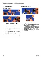
MIL-C-5015 SPEC CONNECTOR’S
Crown Connector Inc’s recommendation is to not use
dielectric grease for this series connector. For similar
model series connectors, the manufacturer should be
contacted for confirmation before applying dielectric
grease. A typical application for this connector is on
David Clark Intercom connections in Aerial Work Plat-
forms.
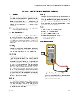
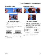
MOLEX CMC SERIES CONNECTORS
The CMC connector family is a sealed, high-density con-
nection system using matte-seal technology for CP
0.635 and 1.50 mm terminals. To guarantee IP6K7 and
IP6K9 sealing, a seal plug option is used. However, the
low-force contacts cannot displace dielectric grease and
create electrical contact. It is possible to use solvents
(i.e. contact cleaner or mineral spirits) for the removal of
improperly applied dielectric grease. The flexbox con-
trol modules from JDES employ this connector system
(for example).
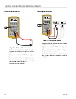
7.4
AMP CONNECTOR
Applying Silicone Dielectric Compound to AMP
Connectors
Silicone Dielectric Compound must be used on the AMP con-
nections for the following reasons:
• To prevent oxidation at the mechanical joint between male
and female pins.
• To prevent electrical malfunction caused by low level con-
ductivity between pins when wet.
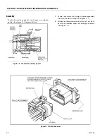
Use the following procedure to apply Silicone Dielectric Com-
pound to the electrical connectors.
1.
To prevent oxidation and low level conductivity, silicone
dielectric grease must be packed completely around
male and female pins on the inside of the connector
after the mating of the housing to the header. This is
easily achieved by using a syringe to fill the header with
silicone dielectric compound, to a point just above the
top of the male pins inside the header. When assem-
bling the housing to the header, it is possible that the
housing will become air locked, thus preventing the
housing latch from engaging.
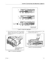
2.
Pierce one of the unused wire seals to allow the trapped
air inside the housing to escape.
3.
Install a hole plug into this and/or any unused wire seal
that has silicone dielectric compound escaping from it.
Содержание 740AJ
Страница 1: ...Service and Maintenance Manual Model 740AJ Prior to S N 0300185827 P N 3121160 October 24 2017 AS NZS...
Страница 2: ......
Страница 51: ...SECTION 2 GENERAL 3121160 2 11 Figure 2 2 Engine Operating Temperature Specifications Ford 4150548 E...
Страница 55: ...SECTION 3 CHASSIS TURNTABLE 3121160 3 3 This page left blank intentionally...
Страница 56: ...SECTION 3 CHASSIS TURNTABLE 3 4 3121160 1 Figure 3 2 Axle and Steering Installation Sheet 1 of 2 0258286 C...
Страница 100: ...SECTION 3 CHASSIS TURNTABLE 3 48 3121160 Figure 3 37 Swing Bearing Tolerance Boom Placement Sheet 1 of 2...
Страница 101: ...SECTION 3 CHASSIS TURNTABLE 3121160 3 49 Figure 3 38 Swing Bearing Tolerance Boom Placement Sheet 2 of 2...
Страница 116: ...SECTION 3 CHASSIS TURNTABLE 3 64 3121160 Figure 3 44 Swing Hub Prior to SN 0300074383...
Страница 124: ...SECTION 3 CHASSIS TURNTABLE 3 72 3121160 Figure 3 45 Swing Drive Hub Fairfield SN 0300074383 through 0300134352...
Страница 180: ...SECTION 3 CHASSIS TURNTABLE 3 128 3121160 1 Figure 3 66 Auxiliary Pump Location 1 AuxiliaryPump 2 HydraulicTank...
Страница 203: ...SECTION 3 CHASSIS TURNTABLE 3121160 3 151 Figure 3 77 EFI Component Location...
Страница 206: ...SECTION 3 CHASSIS TURNTABLE 3 154 3121160 Figure 3 78 ECM EPM Identification ECM EPM...
Страница 213: ...SECTION 3 CHASSIS TURNTABLE 3121160 3 161 Megajector Regulator LockoffSolenoid Figure 3 80 LPG System Components Mixer...
Страница 219: ...SECTION 3 CHASSIS TURNTABLE 3121160 3 167 Figure 3 81 Check Out and Initial Start Up Procedures...
Страница 224: ...SECTION 3 CHASSIS TURNTABLE 3 172 3121160 Figure 3 83 Deutz EMR 2 Troubleshooting Flow Chart...
Страница 225: ...SECTION 3 CHASSIS TURNTABLE 3121160 3 173 Figure 3 84 Deutz EMR 2 Vehicle Side Connection Diagram...
Страница 226: ...SECTION 3 CHASSIS TURNTABLE 3 174 3121160 Figure 3 85 Deutz EMR 2 Engine Side Connection Diagram Sheet 1 of 2...
Страница 227: ...SECTION 3 CHASSIS TURNTABLE 3121160 3 175 Figure 3 86 Deutz EMR 2 Engine Side Connection Diagram Sheet 2 of 2...
Страница 228: ...SECTION 3 CHASSIS TURNTABLE 3 176 3121160 Figure 3 87 EMR 2 Engine Plug Pin Identification...
Страница 229: ...SECTION 3 CHASSIS TURNTABLE 3121160 3 177 Figure 3 88 EMR 2 Vehicle Plug Pin Identification...
Страница 230: ...SECTION 3 CHASSIS TURNTABLE 3 178 3121160 Figure 3 89 EMR2 Fault Codes Sheet 1 of 5...
Страница 231: ...SECTION 3 CHASSIS TURNTABLE 3121160 3 179 Figure 3 90 EMR2 Fault Codes Sheet 2 of 5...
Страница 232: ...SECTION 3 CHASSIS TURNTABLE 3 180 3121160 Figure 3 91 EMR2 Fault Codes Sheet 3 of 5...
Страница 233: ...SECTION 3 CHASSIS TURNTABLE 3121160 3 181 Figure 3 92 EMR2 Fault Codes Sheet 4 of 5...
Страница 234: ...SECTION 3 CHASSIS TURNTABLE 3 182 3121160 Figure 3 93 EMR2 Fault Codes Sheet 5 of 5...
Страница 303: ...SECTION 4 BOOM PLATFORM 3121160 4 31 Figure 4 20 Rotator Assembly HELAC...
Страница 335: ...SECTION 4 BOOM PLATFORM 3121160 4 63 THIS SENSOR ON NON ADE MACHINES ONLY Figure 4 27 UMS Sensor Location...
Страница 336: ...SECTION 4 BOOM PLATFORM 4 64 3121160 Figure 4 28 UMS Module Location ADE MACHINES NON ADE MACHINES...
Страница 425: ...SECTION 5 BASIC HYDRAULIC INFORMATION AND SCHEMATICS 3121160 5 81 Figure 5 131 Variable Displacement Pump Rexroth...
Страница 443: ...SECTION 5 BASIC HYDRAULIC INFORMATION AND SCHEMATICS 3121160 5 99 Figure 5 146 Fault Logic Troubleshooting...
Страница 444: ...SECTION 5 BASIC HYDRAULIC INFORMATION AND SCHEMATICS 5 100 3121160 Figure 5 147 Fault Logic Troubleshooting...
Страница 445: ...SECTION 5 BASIC HYDRAULIC INFORMATION AND SCHEMATICS 3121160 5 101 Figure 5 148 Fault Logic Troubleshooting...
Страница 460: ...SECTION 5 BASIC HYDRAULIC INFORMATION AND SCHEMATICS 5 116 3121160 NOTES...
Страница 467: ...SECTION 6 JLG CONTROL SYSTEM 3121160 6 7 Figure 6 2 ADE Block Diagram...
Страница 471: ...SECTION 6 JLG CONTROL SYSTEM 3121160 6 11 Figure 6 6 Analyzer Flow Chart Prior to Version 5 X Software Sheet 4 of 4...
Страница 473: ...SECTION 6 JLG CONTROL SYSTEM 3121160 6 13 Figure 6 8 Analyzer Flow Chart Version 5 X Software Sheet 2 of 4...
Страница 534: ...SECTION 6 JLG CONTROL SYSTEM 6 74 3121160 NOTES...
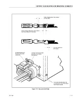
Страница 545: ...SECTION 7 BASIC ELECTRICAL INFORMATION SCHEMATICS 3121160 7 11 Figure 7 15 Connector Installation...
Страница 580: ...SECTION 7 BASIC ELECTRICAL INFORMATION SCHEMATICS 7 46 3121160 NOTES...
Страница 581: ......


