

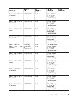
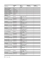
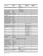
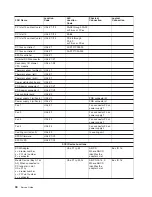


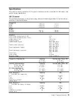
FRU
Name
Location
Code
AIX
Location
Code
Physical
Connection
Logical
Connection
PCI
slot
13
content
(card)
U0.4-P1-I13
FA-08
through
FA-0F
or
FB-xx
or
FC-xx
PCI
slot
14
U0.4-P1/I14
E0-66
PCI
slot
14
content
(card)
U0.4-P1/I14
FD-08
through
FD-0F
or
FE-xx
or
FF-xx
PCI
bus
controller
1
U0.4-P1
00-FFF7C09000
PCI
bus
controller
2
U0.4-P1
00-FFF7C0A000
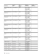
SPCN
controller
U0.4-P1
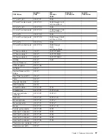
External
SCSI
connector
U0.4-P1/Z1
Secondary
I/O
drawer
VPD
module
U0.4-L1-N1
Thermal
sensor
(ambient)
U0.4-L1
Thermal
sensor
(left)
U0.4-P1
Thermal
sensor
(right)
U0.4-P1
Power
distribution
board
U0.4-X1
PDB
power
connector
1
U0.4-X1/V1
PDB
power
connector
2
U0.4-X1/V2
Fan
controller
card
U0.4-X2
Power
supply
1
(w/Fan
5)
U0.4-V1
PDB
connector
J2
Power
supply
2
(w/Fan
6)
U0.4-V2
PDB
connector
J1
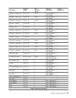
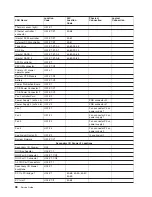
Fan
1
U0.4-F1
Fan
connector
P3
on
power
supply
1
Fan
2
U0.4-F2
Fan
connector
P3
on
power
supply
1
Fan
3
U0.4-F3
Fan
connector
P3
on
power
supply
2
Fan
4
U0.4-F4
Fan
connector
P3
on
power
supply
2
Cooling
unit
(w/fan
9)
U0.4-F9
In
cooling
unit
SPCN
firmware
U0.4-P1/Y3
SPCN
VPD
U0.4-P1/Y4
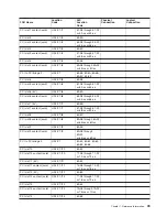
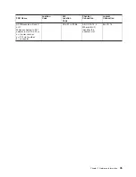
SCSI
Device
Locations
SCSI
Adapter
x
=
drawer
number
y
=
PCI
slot
number
z
=
connector
U0.x-P1-ly-Zz
AB-CD
Where
AB-CD
identifies
the
adapter’s
slot
Bus
ID
15
Media
Device
(Bay
A1
or
A2)
When
connected
to
PCI
adapter
in
slot
U0.x-P1-ly
x
=
drawer
number
y
=
PCI
slot
number
z
=
connector
U0.x-P1-ly-Zz-Ai
AB-CD-00-15,
0
Where
AB-CD
identifies
the
adapter’s
slot
Bus
ID
15
44
Service
Guide
Содержание RS/6000 Enterprise Server M80
Страница 1: ...RS 6000 Enterprise Server Model M80 Eserver pSeries 660 Model 6M1 Service Guide SA38 0571 01...
Страница 10: ...x Service Guide...
Страница 14: ...xiv Service Guide...
Страница 16: ...xvi Service Guide...
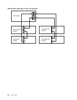
Страница 22: ...Data Flow 4 Service Guide...
Страница 28: ...CEC Drawer Front View With Bezel Removed 3 2 1 1 Power On Off LED 2 Fan 2 3 Fan 1 10 Service Guide...
Страница 30: ...CEC Card Cage Rear of CEC drawer viewed from top cover removed 12 Service Guide...
Страница 84: ...66 Service Guide...
Страница 176: ...158 Service Guide...
Страница 376: ...358 Service Guide...
Страница 430: ...412 Service Guide...
Страница 445: ...3 Insert the memory module firmly into the connector Chapter 10 Removal and Replacement Procedures 427...
Страница 476: ...7 Remove the screws that connect the carrier to the CD ROM Replacement Replace in reverse order 458 Service Guide...
Страница 485: ...Chapter 11 Parts Information This chapter contains parts information for the system 467...
Страница 486: ...CEC Drawer Card Assembly 9 468 Service Guide...
Страница 488: ...CEC Drawer Backplane 5 2a 1 2 3 4 470 Service Guide...
Страница 490: ...CEC Drawer Power Supplies 1 2 3 4 5 6 7 8 9 472 Service Guide...
Страница 492: ...CEC Drawer Fan Assemblies 2 1 3 4 5 6 8 9 10 11 12 13 7 14 474 Service Guide...
Страница 494: ...I O Drawer 1 2 3 4 5 6 7 8 9 10 11 16 17 18 19 20 12 14 13 13 15 21 22 23 24 26 25 27 476 Service Guide...
Страница 496: ...7 8 9 10 6 1 2 3 4 4 5 478 Service Guide...
Страница 508: ...490 Service Guide...
Страница 520: ...502 Service Guide...
Страница 522: ...504 Service Guide...
Страница 526: ...508 Service Guide...
Страница 542: ...error Handle unexpected modem responses expect 8 r or 7 r or 6 r or 4 r or 3 r delay 2 done 524 Service Guide...
Страница 558: ...540 Service Guide...
Страница 565: ......
Страница 566: ...Printed in USA September 2001 SA38 0571 01...
Страница 567: ...Spine information RS 6000 Enterprise Server Model M80 Eserver pSeries 660 Model 6M1 Service Guide SA38 0571 01...


