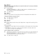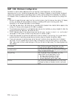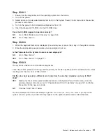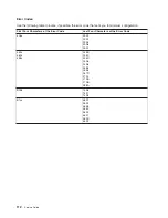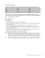
Step
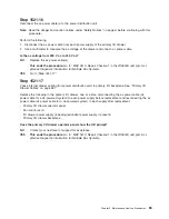
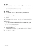
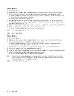
1523-16
Reconnect
the
ac
power
cable(s)
to
the
power
distribution
unit.
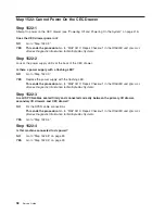
Note:
Read
the
danger
and
caution
notices
under
“Safety
Notices”
on
page
xi
before
continuing
with
this
procedure.
Perform
the
following:
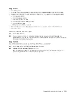
1.
Disconnect
the
ac
power
cable
from
each
power
supply
of
secondary
I/O
drawer.
2.
Use
a
multimeter
to
measure
the
ac
voltage
at
the
drawer
end
of
each
ac
power
cable.
Is
the
ac
voltage
from
200
V
ac
to
240
V
ac?
NO
Replace
the
ac
power
cable(s).
This
ends
the
procedure.
Go
to
″
MAP
0410:
Repair
Checkout
″
in
the
RS/6000
and
Eserver
pSeries
Diagnostic
Information
for
Multiple
Bus
Systems
.
YES
Go
to
“Step
1523-17.”
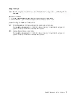
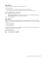
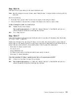
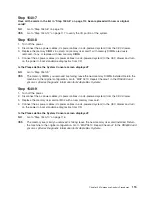
Step
1523-17
Check
internal
drawer
cabling
from
power
distribution
card
to
secondary
I/O
backplane.
See
“Secondary
I/O
Drawer
Cables”
on
page
483.
Replace
the
following
in
the
secondary
I/O
drawer,
one
at
a
time,
disconnecting
the
ac
power
cable
(dc
power
cable
for
a
dc-powered
system)
to
each
power
supply
before
replacement
and
reconnecting
the
ac
power
cable
(dc
power
cable
for
a
dc-powered
system)
to
each
supply
after
replacement:
v
Secondary
I/O
drawer
operator
panel
v
Fan
control
card
v
Power
distribution
card
v
I/O
drawer
power
supply
(including
redundant
power
supply,
if
present)
v
Secondary
I/O
drawer
backplane
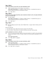
Does
the
secondary
I/O
drawer
operator
panel
turn
on
the
power
present
LED?
NO
Contact
your
next
level
of
support
for
assistance.
YES
This
ends
the
procedure.
Go
to
″
MAP
0410:
Repair
Checkout
″
in
the
RS/6000
and
Eserver
pSeries
Diagnostic
Information
for
Multiple
Bus
Systems
.
Chapter
3.
Maintenance
Analysis
Procedures
103
Содержание RS/6000 Enterprise Server M80
Страница 1: ...RS 6000 Enterprise Server Model M80 Eserver pSeries 660 Model 6M1 Service Guide SA38 0571 01...
Страница 10: ...x Service Guide...
Страница 14: ...xiv Service Guide...
Страница 16: ...xvi Service Guide...
Страница 22: ...Data Flow 4 Service Guide...
Страница 28: ...CEC Drawer Front View With Bezel Removed 3 2 1 1 Power On Off LED 2 Fan 2 3 Fan 1 10 Service Guide...
Страница 30: ...CEC Card Cage Rear of CEC drawer viewed from top cover removed 12 Service Guide...
Страница 84: ...66 Service Guide...
Страница 176: ...158 Service Guide...
Страница 376: ...358 Service Guide...
Страница 430: ...412 Service Guide...
Страница 445: ...3 Insert the memory module firmly into the connector Chapter 10 Removal and Replacement Procedures 427...
Страница 476: ...7 Remove the screws that connect the carrier to the CD ROM Replacement Replace in reverse order 458 Service Guide...
Страница 485: ...Chapter 11 Parts Information This chapter contains parts information for the system 467...
Страница 486: ...CEC Drawer Card Assembly 9 468 Service Guide...
Страница 488: ...CEC Drawer Backplane 5 2a 1 2 3 4 470 Service Guide...
Страница 490: ...CEC Drawer Power Supplies 1 2 3 4 5 6 7 8 9 472 Service Guide...
Страница 492: ...CEC Drawer Fan Assemblies 2 1 3 4 5 6 8 9 10 11 12 13 7 14 474 Service Guide...
Страница 494: ...I O Drawer 1 2 3 4 5 6 7 8 9 10 11 16 17 18 19 20 12 14 13 13 15 21 22 23 24 26 25 27 476 Service Guide...
Страница 496: ...7 8 9 10 6 1 2 3 4 4 5 478 Service Guide...
Страница 508: ...490 Service Guide...
Страница 520: ...502 Service Guide...
Страница 522: ...504 Service Guide...
Страница 526: ...508 Service Guide...
Страница 542: ...error Handle unexpected modem responses expect 8 r or 7 r or 6 r or 4 r or 3 r delay 2 done 524 Service Guide...
Страница 558: ...540 Service Guide...
Страница 565: ......
Страница 566: ...Printed in USA September 2001 SA38 0571 01...
Страница 567: ...Spine information RS 6000 Enterprise Server Model M80 Eserver pSeries 660 Model 6M1 Service Guide SA38 0571 01...

