
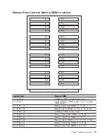

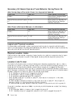


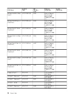

Location
Code
Memory
DIMMs
U1.1-P1-M1.5
x8
Memory
Octal
C
(DIMMs
5,
6,
13,
14,
21,
22,
29,
30)
U1.1-P1-M1.6
x4
Memory
Quad
C
Even
(DIMMs
6,
14,
22,
30)
U1.1-P1-M1.7
x4
Memory
Quad
D
Odd
(DIMMs
7,
15,
23,
31)
U1.1-P1-M1.7
x8
Memory
Octal
D
(DIMMs
7,
8,
15,
16,
23,
24,
31,
32)
U1.1-P1-M1.8
x4
Memory
Quad
D
Even
(DIMMs
8,
16,
24,
32)
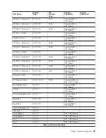
U1.1-P1-M2.n
Individual
Memory
DIMMs
on
Riser
Card
2
(n
denotes
DIMM
number)
U1.1-P1-M2.1
x4
Memory
Quad
A
Odd
(DIMMs
1,
9,
17,
25)
U1.1-P1-M2.1
x8
Memory
Octal
A
(DIMMs
1,
2,
9,
10,
17,
18,
25,
26)
U1.1-P1-M2.1
x32
All
Memory
DIMMs
on
Riser
Card
2
U1.1-P1-M2.2
x4
Memory
Quad
A
Even
(DIMMs
2,
10,
18,
26)
U1.1-P1-M2.3
x4
Memory
Quad
B
Odd
(DIMMs
3,
11,
19,
27)
U1.1-P1-M2.3
x8
Memory
Octal
B
(DIMMs
3,
4,
11,
12,
19,
20,
27,
28)
U1.1-P1-M2.4
x4
Memory
Quad
B
Even
(DIMMs
4,
12,
20,
28)
U1.1-P1-M2.5
x4
Memory
Quad
C
Odd
(DIMMs
5,
13,
21,
29)
U1.1-P1-M2.5
x8
Memory
Octal
C
(DIMMs
5,
6,
13,
14,
21,
22,
29,
30)
U1.1-P1-M2.6
x4
Memory
Quad
C
Even
(DIMMs
6,
14,
22,
30)
U1.1-P1-M2.7
x4
Memory
Quad
D
Odd
(DIMMs
7,
15,
23,
31)
U1.1-P1-M2.7
x8
Memory
Octal
D
(DIMMs
7,
8,
15,
16,
23,
24,
31,
32)
U1.1-P1-M2.8
x4
Memory
Quad
D
Even
(DIMMs
8,
16,
24,
32)
For
physical
locations,
see
“Memory
Riser
Card
and
Memory
DIMM
Locations”
on
page
19.
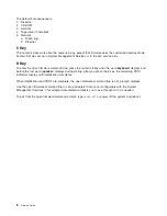
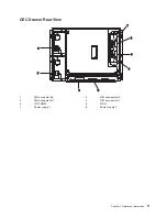
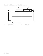
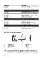
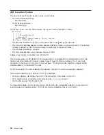
Primary
I/O
Drawer
Operator
Panel
R
1
2
8
9
5
3
7
4
6
!
1
Power
on/off
button
2
Power
on/off
LED
3
Operator
panel
display
4
Speaker
5
Serial
number
plate
6
Reset
icon
7
Reset
button
8
Service
use
only
9
Disturbance
or
system
attention
LED
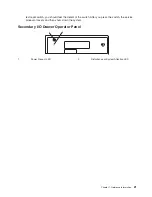
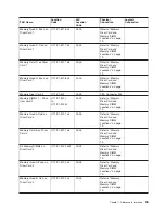
Note:
You
must
activate
the
service
processor
reset
button
very
carefully.
An
insulated
paper
clip
is
recommended.
Unbend
the
clip
so
that
it
has
a
straight
section
about
two
inches
long.
Insert
the
clip
straight
into
the
hole,
keeping
the
clip
perpendicular
to
the
plastic
bezel.
When
you
engage
the
20
Service
Guide
Содержание RS/6000 Enterprise Server M80
Страница 1: ...RS 6000 Enterprise Server Model M80 Eserver pSeries 660 Model 6M1 Service Guide SA38 0571 01...
Страница 10: ...x Service Guide...
Страница 14: ...xiv Service Guide...
Страница 16: ...xvi Service Guide...
Страница 22: ...Data Flow 4 Service Guide...
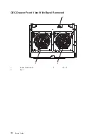
Страница 28: ...CEC Drawer Front View With Bezel Removed 3 2 1 1 Power On Off LED 2 Fan 2 3 Fan 1 10 Service Guide...
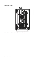
Страница 30: ...CEC Card Cage Rear of CEC drawer viewed from top cover removed 12 Service Guide...
Страница 84: ...66 Service Guide...
Страница 176: ...158 Service Guide...
Страница 376: ...358 Service Guide...
Страница 430: ...412 Service Guide...
Страница 445: ...3 Insert the memory module firmly into the connector Chapter 10 Removal and Replacement Procedures 427...
Страница 476: ...7 Remove the screws that connect the carrier to the CD ROM Replacement Replace in reverse order 458 Service Guide...
Страница 485: ...Chapter 11 Parts Information This chapter contains parts information for the system 467...
Страница 486: ...CEC Drawer Card Assembly 9 468 Service Guide...
Страница 488: ...CEC Drawer Backplane 5 2a 1 2 3 4 470 Service Guide...
Страница 490: ...CEC Drawer Power Supplies 1 2 3 4 5 6 7 8 9 472 Service Guide...
Страница 492: ...CEC Drawer Fan Assemblies 2 1 3 4 5 6 8 9 10 11 12 13 7 14 474 Service Guide...
Страница 494: ...I O Drawer 1 2 3 4 5 6 7 8 9 10 11 16 17 18 19 20 12 14 13 13 15 21 22 23 24 26 25 27 476 Service Guide...
Страница 496: ...7 8 9 10 6 1 2 3 4 4 5 478 Service Guide...
Страница 508: ...490 Service Guide...
Страница 520: ...502 Service Guide...
Страница 522: ...504 Service Guide...
Страница 526: ...508 Service Guide...
Страница 542: ...error Handle unexpected modem responses expect 8 r or 7 r or 6 r or 4 r or 3 r delay 2 done 524 Service Guide...
Страница 558: ...540 Service Guide...
Страница 565: ......
Страница 566: ...Printed in USA September 2001 SA38 0571 01...
Страница 567: ...Spine information RS 6000 Enterprise Server Model M80 Eserver pSeries 660 Model 6M1 Service Guide SA38 0571 01...


