


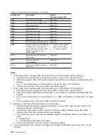


Step
1540-28
The
last
I/O
drawer
connected
was
a
secondary
I/O
drawer.
If
the
power
is
on,
turn
off
the
power.
Reconnect
the
next
I/O
drawer
in
the
configuration
you
recorded
earlier
in
this
MAP.
Note:
The
I/O
drawers
should
be
cabled
as
shown
in
“Cabling
the
CEC
Drawer,
Primary
I/O
Drawer,
and
Secondary
I/O
Drawer(s)”
on
page
46.
Be
sure
to
look
at
both
RIO
cables
and
SPCN
cables.
Go
to
“Step
1540-29”
Step
1540-29
1.
Turn
on
the
power
to
boot
standalone
diagnostics
from
CD.
2.
If
the
Please
define
the
System
Console
screen
is
displayed,
follow
directions
to
select
the
system
console.
3.
Use
the
Display
Configuration
and
Resource
List
to
list
all
attached
devices
and
adapters
(refer
to
the
RS/6000
and
Eserver
pSeries
Diagnostic
Information
for
Multiple
Bus
Systems
if
necessary).
4.
Check
that
all
attached
devices
and
adapters
are
listed.
Did
the
Please
define
the
System
Console
screen
display
and
are
all
attached
devices
and
adapters
listed?
NO
Is
the
SRC
that
sent
you
to
MAP
1540
20FB99xy?
NO
Go
to
“Step
1540-30.”
YES
Go
to
“Step
1540-41”
on
page
134.
YES
Is
there
another
I/O
drawer
to
connect?
NO
The
problem
has
changed.
Call
your
next
level
of
support.
YES
Go
to
“Step
1540-28.”
Step
1540-30
The
problem
is
in
the
last
secondary
I/O
drawer
that
was
connected.
To
deconfigure
this
secondary
I/O
drawer,
perform
the
following
steps.
Are
there
any
adapters
in
slots
1,
2,
3,
or
4?
NO
Go
to
“Step
1540-31”
on
page
129.
YES
Go
to
“Step
1540-33”
on
page
129.
128
Service
Guide
Содержание RS/6000 Enterprise Server M80
Страница 1: ...RS 6000 Enterprise Server Model M80 Eserver pSeries 660 Model 6M1 Service Guide SA38 0571 01...
Страница 10: ...x Service Guide...
Страница 14: ...xiv Service Guide...
Страница 16: ...xvi Service Guide...
Страница 22: ...Data Flow 4 Service Guide...
Страница 28: ...CEC Drawer Front View With Bezel Removed 3 2 1 1 Power On Off LED 2 Fan 2 3 Fan 1 10 Service Guide...
Страница 30: ...CEC Card Cage Rear of CEC drawer viewed from top cover removed 12 Service Guide...
Страница 84: ...66 Service Guide...
Страница 176: ...158 Service Guide...
Страница 376: ...358 Service Guide...
Страница 430: ...412 Service Guide...
Страница 445: ...3 Insert the memory module firmly into the connector Chapter 10 Removal and Replacement Procedures 427...
Страница 476: ...7 Remove the screws that connect the carrier to the CD ROM Replacement Replace in reverse order 458 Service Guide...
Страница 485: ...Chapter 11 Parts Information This chapter contains parts information for the system 467...
Страница 486: ...CEC Drawer Card Assembly 9 468 Service Guide...
Страница 488: ...CEC Drawer Backplane 5 2a 1 2 3 4 470 Service Guide...
Страница 490: ...CEC Drawer Power Supplies 1 2 3 4 5 6 7 8 9 472 Service Guide...
Страница 492: ...CEC Drawer Fan Assemblies 2 1 3 4 5 6 8 9 10 11 12 13 7 14 474 Service Guide...
Страница 494: ...I O Drawer 1 2 3 4 5 6 7 8 9 10 11 16 17 18 19 20 12 14 13 13 15 21 22 23 24 26 25 27 476 Service Guide...
Страница 496: ...7 8 9 10 6 1 2 3 4 4 5 478 Service Guide...
Страница 508: ...490 Service Guide...
Страница 520: ...502 Service Guide...
Страница 522: ...504 Service Guide...
Страница 526: ...508 Service Guide...
Страница 542: ...error Handle unexpected modem responses expect 8 r or 7 r or 6 r or 4 r or 3 r delay 2 done 524 Service Guide...
Страница 558: ...540 Service Guide...
Страница 565: ......
Страница 566: ...Printed in USA September 2001 SA38 0571 01...
Страница 567: ...Spine information RS 6000 Enterprise Server Model M80 Eserver pSeries 660 Model 6M1 Service Guide SA38 0571 01...


