UPS5000-S-1200 kVA
User Manual
2 Overview
Issue 04 (2019-06-25)
Copyright © Huawei Technologies Co., Ltd.
34
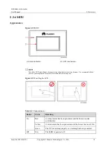
The indicator on the LCD panel is yellow when the bypass supplies power in non-ECO mode.
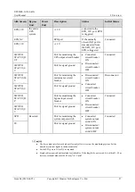
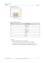
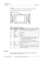
The ports of the LCD screen are located at the side of the LCD screen.
Figure 2-24
LCD screen ports
Table 2-12
Description of LCD screen ports
No.
Port Name
Description
1
MUS05A
(DB26)
Connects to the MDU and monitoring interface card
2
FE
Network port
3
CAN
Reserved
4
RS485_1
Reserved
5
USB Host
After installing the WiFi module, connect the WiFi
module to the UPS using the app on the mobile phone to
obtain the initial startup password.
Insert the USB flash drive, import and export the
configuration file, export run logs, and upgrade software.
6
RST
Restart switch for the MDU
7
SD
Reserved
8
DIP switch
Implements specific functions by using the DIP switch and
specific buttons; controls the CAN communication build-out
resistor in a parallel system
Functions
The monitor display unit (MDU) allows for general UPS operations, parameter setting,
viewing of running status and alarms, and so on.


