Removal and Replacement Procedures
Front Panel LED Assembly
To remove the front panel LED assembly:
1. Prepare the server for a non-hot-plug procedure. Refer to “Preparing the Server for
Non-Hot-Plug Procedures” in this chapter.
2. Remove the front bezel door (tower model only), and lay the server on its side with the
access panel facing upward. Refer to “Removing the Front Bezel Door (Tower Model
Only)” in this chapter.
3. Remove the rack bezel (rack model only). Refer to “Rack Bezel (Rack Model Only)” in
this chapter.
4. Remove the access panel. Refer to “Removing the Access Panel” in this chapter.
5. Remove the hot-plug fans. Refer to “Hot-Plug Fans (Processor and I/O)” in this chapter.
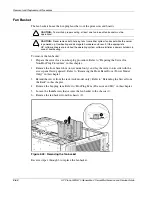
6. Remove the fan basket. Refer to “Fan Basket” in this chapter.
7. Unscrew and move aside the processor fan bracket. It is not necessary to disconnect
cables or remove this component completely for this procedure. Refer to “Processor Fan
Bracket” in this chapter.
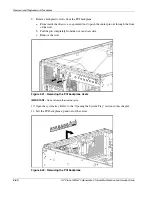
8. Disconnect the front panel LED assembly from the power backplane.
Figure 2-55: Removing the front panel LED assembly power cable
9. Disconnect the cable from all cable guide clips, and pass it through the cable guide
opening toward the front of the server.
2-64
HP ProLiant ML570 Generation 2 Server Maintenance and Service Guide
Содержание ProLiant ML570 Generation 2
Страница 6: ......


