


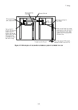
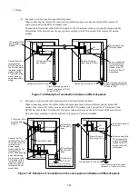
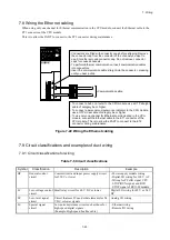
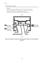
7. Wiring
7-9
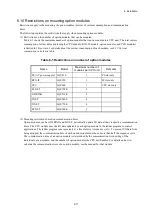
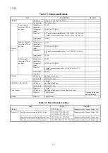
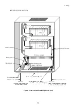
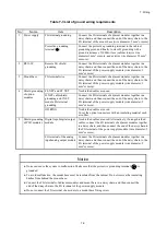
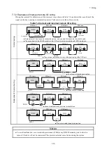
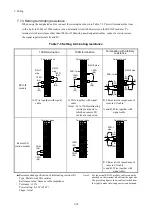
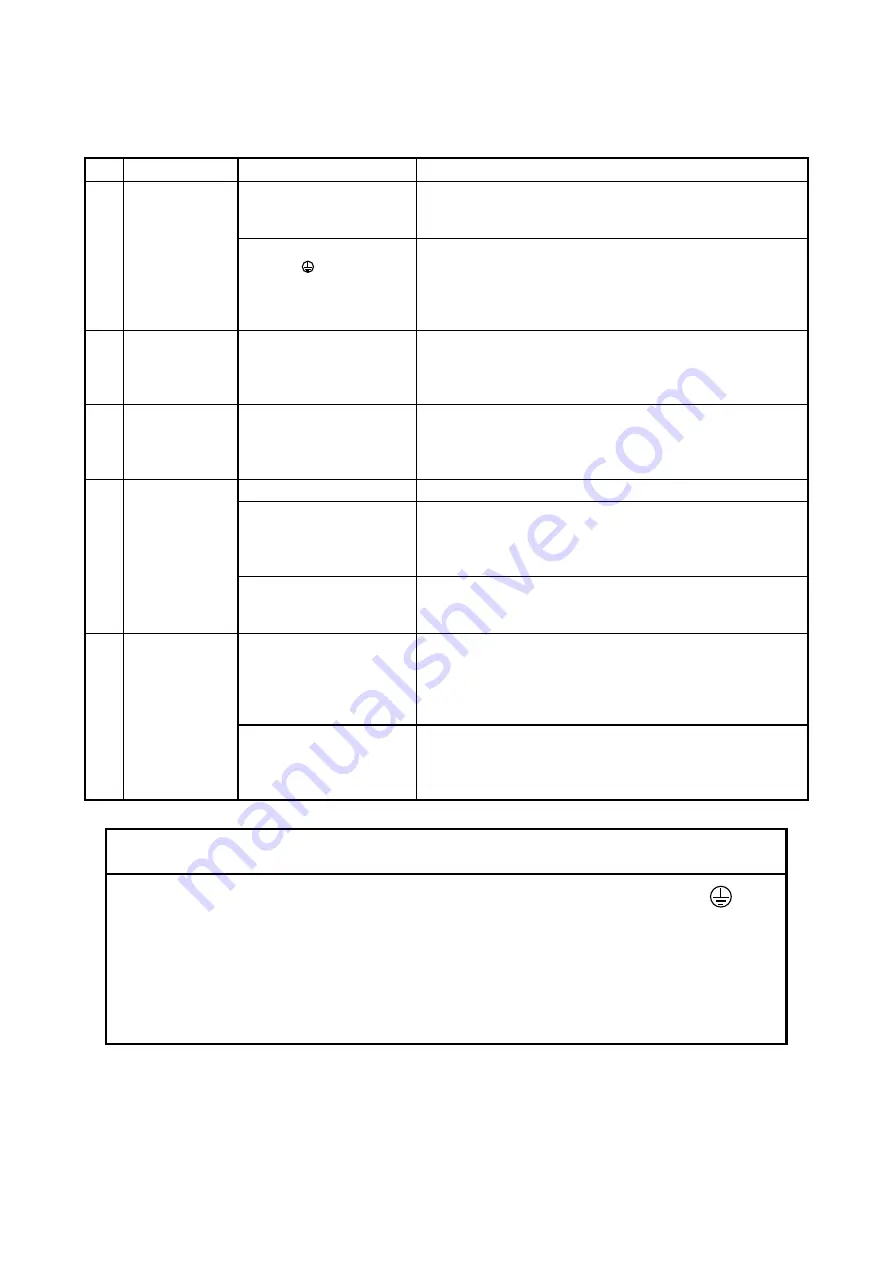
Table 7-3 List of ground wiring requirements
No.
Name
Item
Description
1
Power supply
FG terminal grounding
Connect the FG terminals of adjacent modules together in a
daisy chain, and then connect the end of the daisy chain to the
FG terminal of the mount base (wire diameter: 2 mm
2
or more).
Protective grounding
terminal ( )
Connect the protective grounding terminal to the cabinet
grounding point, and finally to class D grounding with a
ground resistance of 100Ω or less (cabinet interior wire
diameter 2 mm
2
or more, and exterior wire diameter 5.5 mm
2
or more).
2
RI/O-IF
Remote I/O shield
grounding
Connect the FG terminals of adjacent modules together in a
daisy chain, and then connect the end of the daisy chain to the
FG terminal of the power supply module (wire diameter: 2
mm
2
or more).
3
Mount base
FG terminal wire
Connect the FG terminals of adjacent modules together in a
daisy chain, and then connect the end of the daisy chain to the
FG terminal of the power supply module (wire diameter: 2
mm
2
or more).
4
Shield grounding
of option
modules
FL.NET and ET.NET
No shielded cables are used.
D.NET cable shield
grounding and J.NET
module FG terminal
grounding
Connect the FG terminals of adjacent modules together in a
daisy chain, and then connect the end of the daisy chain to the
FG terminal of the power supply module (wire diameter: 2
mm
2
or more).
OD.RING
No shielded cables are used.
Cover the optical connectors with an insulating material such
as rubber.
5
Shield grounding
of PI/O modules
Digital input/digital output
module
No shielded cables are used. Alternatively, if using shielded
cables, connect the FG terminals of adjacent modules together
in a daisy chain, and then connect the end of the daisy chain to
the FG terminal of the power supply module (wire diameter: 2
mm
2
or more).
FG terminal of the analog
input/analog output module
Connect the FG terminals of adjacent modules together in a
daisy chain, and then connect the end of the daisy chain to the
FG terminal of the power supply module (wire diameter: 2
mm
2
or more).
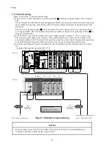
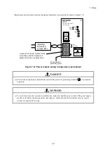
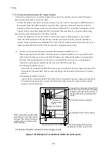
Notice
● Noise can cause the system to malfunction. Make sure that the protective grounding terminal ( ) is
grounded.
● To avoid malfunction, the mount base must be insulated from the cabinet. Do not remove the insulating
bushes from behind the mount base.
● Connect the FG terminals of adjacent modules and mount base in a daisy chain, and then connect the
end of the daisy chain to the FG terminal of the power supply module.
● Do not connect the FG terminal of a module to a mount base fixing screw.
Содержание S10VE
Страница 1: ...User s Manual General Description SEE 1 001 A ...
Страница 2: ...User s Manual General Description ...
Страница 27: ...S 24 Revision History Revision No History revision details Issue date Remarks A New edition Oct 2019 ...
Страница 53: ...This page is intentionally left blank ...
Страница 59: ...This page is intentionally left blank ...
Страница 67: ...This page is intentionally left blank ...
Страница 75: ...This page is intentionally left blank ...
Страница 77: ...This page is intentionally left blank ...
Страница 103: ...This page is intentionally left blank ...
Страница 129: ...This page is intentionally left blank ...
Страница 295: ...This page is intentionally left blank ...
Страница 309: ...This page is intentionally left blank ...
Страница 341: ...This page is intentionally left blank ...
Страница 345: ...This page is intentionally left blank ...
Страница 475: ...This page is intentionally left blank ...
Страница 489: ...This page is intentionally left blank ...
Страница 505: ......
Страница 506: ...This page is intentionally left blank ...


