7. Wiring
7-8
7.4 Ground wiring
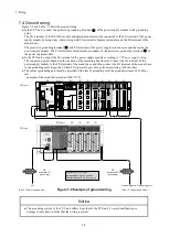
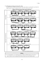
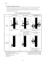
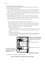
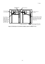
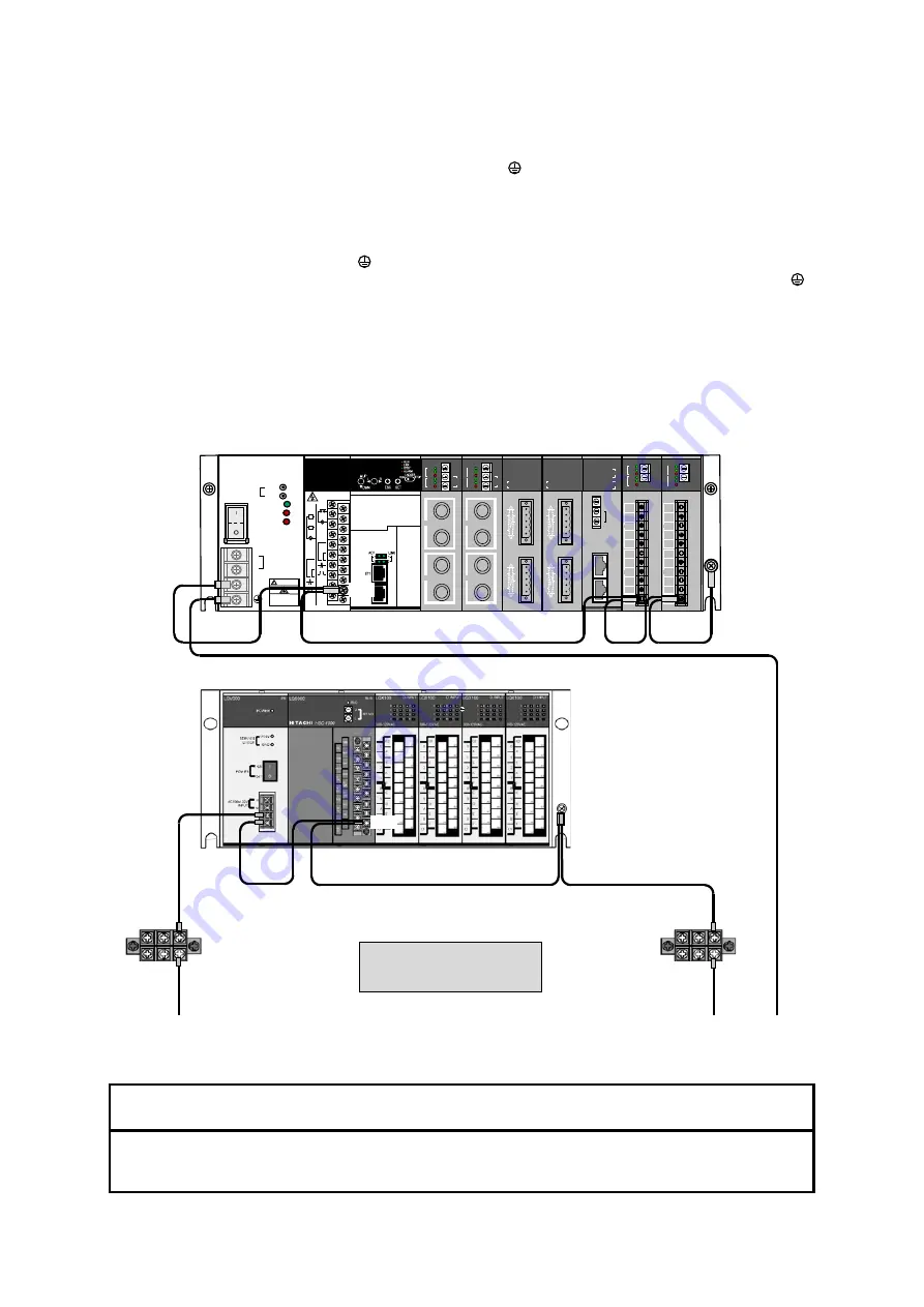
Figure 7-9 and Table 7-3 describe ground wiring.
● In the CPU unit, connect the protective grounding terminal ( ) of the power supply module to the grounding
point.
The FG terminals of the RI/O-IF module and option modules must be connected to the FG terminal of the power
supply module by using daisy-chain wiring with FG terminals of adjacent modules and the FG terminal of the
mount base.
The protective grounding terminal ( ) and FG terminal of the power supply module are connected inside the
power supply module. The FG terminals of modules are grounded via the protective grounding terminal ( ) of
the power supply module.
● In the PI/O unit, connect the LG terminal of the power supply module according to
7.3 Power supply wiring
.
The connection points depend on the location of the insulating transformer. Connect the FG terminal of the
power supply module to the FG terminal of the mount base, and then connect the FG terminal of the mount base
to the grounding point. Keep the LG and FG separate to prevent one from interfering with the other.
● The cabinet grounding point must be provided with class D grounding with the ground resistance of 100Ω or
less.
- Example of the mount base (model: HSC-1770)
Figure 7-9 Example of ground wiring
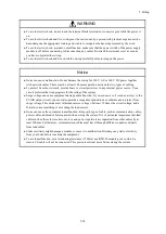
Notice
● The grounding system of the CPU unit differs from that of the PI/O unit. To avoid malfunction or
damage to a module, confirm that the wiring is correct.
I/O
I/O
I/O
RUN
ALARM
ERR
10BASE-T
100BASE-TX
CH 1
MAIN
/SUB
U
L
ST.No.
CH2
TX/RX
100M
10M
TX/RX
100M
10M
CH 1
CH2
LQE260-E ET.NET
OC
OV
LQV410
PS
DC5V
HITACHI
100-120VAC 144VA 50/60Hz
100-110DC 132W
GND
POWER
H
+
FG
N
-
OFF
ON
P
O
W
E
R
INPUT
100-120VAC
100-110DC
SERVICE
CHECK
警告
WARNING
!
感電危険触れるな
Hazardous voltage
will cause death or
severe injury
LQE950
RI/O-IF
RI/O
STOP
STOP
/RUN
SHD
PCsOK
100VAC
100VDC
SHD
SHD
TERM
150Ω
TERM
100Ω
SHD
FG
L
A
B
100VAC
100VDC
TERM
150Ω
TERM
100Ω
A
B
RI/O1
RI/O2
L
PS
RI/O-IF
CPU
I/O
I/O
I/O
I/O
FG (B9)
TB
(collective LG
grounding)
TB
(collective FG
grounding)
Diameter of FG/LG wire
Inside cabinet: 2 mm
2
or more
Outside cabinet: 5.5 mm
2
or more
LG
(See 7.3
Power supply wiring
.)
Grounding point
(See 7.3
Power supply wiring
.)
LG
FG
ST (RI/O)
I/O
I/O
I/O
I/O
FG
FG
LQE540-E J.NET
N1
TX
RX
ER
N2
TR
RX
ERR
TYPE-M521
MODU
No.
BIT
RATE
TERM
A
B
SG
SHD
TERM
A
B
SG
SHD
FG
N1
N1
LQE540-E J.NET
N1
TX
RX
ER
N2
TR
RX
ERR
TYPE-M521
MODU
No.
BIT
RATE
TERM
A
B
SG
SHD
TERM
A
B
SG
SHD
FG
N1
N1
PR
SR
TX
RX
TX
LQE510-E OD.RING
PR
TR
RX
ERR
SR
TR
RX
ERR
CPL
No.
MODU
No.
U
L
RX
PR
SR
TX
RX
TX
LQE510-E OD.RING
PR
TR
RX
ERR
SR
TR
RX
ERR
CPL
No.
MODU
No.
U
L
RX
LQE770-E
D.NET
MODU
No.
MS
NS
CH0
CH1
CH0
CH1
LQE770-E
D.NET
MODU
No.
MS
NS
CH0
CH1
CH0
CH1
Grounding point
CPU unit
PI/O unit
LQP600
CPU
FG (B9)
Содержание S10VE
Страница 1: ...User s Manual General Description SEE 1 001 A ...
Страница 2: ...User s Manual General Description ...
Страница 27: ...S 24 Revision History Revision No History revision details Issue date Remarks A New edition Oct 2019 ...
Страница 53: ...This page is intentionally left blank ...
Страница 59: ...This page is intentionally left blank ...
Страница 67: ...This page is intentionally left blank ...
Страница 75: ...This page is intentionally left blank ...
Страница 77: ...This page is intentionally left blank ...
Страница 103: ...This page is intentionally left blank ...
Страница 129: ...This page is intentionally left blank ...
Страница 295: ...This page is intentionally left blank ...
Страница 309: ...This page is intentionally left blank ...
Страница 341: ...This page is intentionally left blank ...
Страница 345: ...This page is intentionally left blank ...
Страница 475: ...This page is intentionally left blank ...
Страница 489: ...This page is intentionally left blank ...
Страница 505: ......
Страница 506: ...This page is intentionally left blank ...

