


7. Wiring
7-16
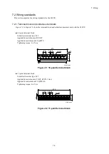
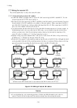
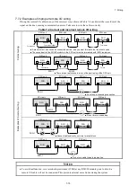
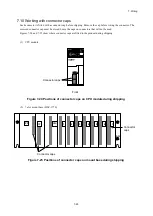
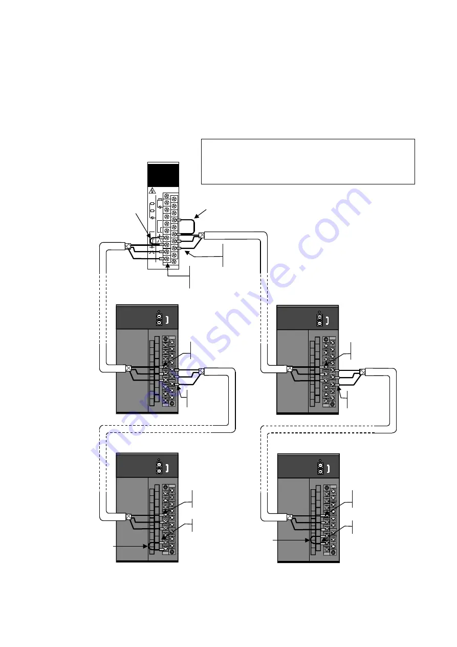
7.7.3 Examples of cable wiring
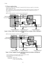
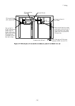
(1) When connecting cables with different characteristics to the RI/O-1 and RI/O-2 ports
Figure 7-16 shows a wiring example for a scenario in which cables with different characteristics connect
to the RI/O-1 port and RI/O-2 port of the CPU module.
- For details on how to set the terminating resistance, see
7.7.4 Setting terminating resistance
.
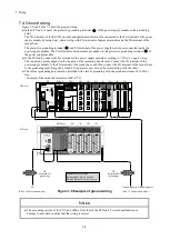
- For details on ground wiring, see
7.4 Ground wiring
.
Figure 7-16 Wiring example when using cables with different characteristics
LQS010
RI/O
HITACHI
HSC-1000
RI/O
ST.NO
U
L
FIX
COM
HOLD
RI/
01A
RI/
01B
SHD
150
Ω
COM
100
Ω
128M
64M
32M
RI/
02A
COM
RI/
02B
SHD
FG
NC
LQS010
RI/O
HITACHI
HSC-1000
RI/O
ST.NO
U
L
FIX
COM
HOLD
RI/
01A
RI/
01B
SHD
150
Ω
COM
100
Ω
128M
64M
32M
RI/
02A
COM
RI/
02B
SHD
FG
NC
LQS010
RI/O
HITACHI
HSC-1000
RI/O
ST.NO
U
L
FIX
COM
HOLD
RI/
01A
RI/
01B
SHD
150
Ω
COM
100
Ω
128M
64M
32M
RI/
02A
COM
RI/
02B
SHD
FG
NC
LQS010
RI/O
HITACHI
HSC-1000
RI/O
ST.NO
U
L
FIX
COM
HOLD
RI/
01A
RI/
01B
SHD
150
Ω
COM
100
Ω
128M
64M
32M
RI/
02A
COM
RI/
02B
SHD
FG
NC
LQE950
RI/O-IF
RI/O
STOP
STOP
/RUN
SHD
PCsOK
100VAC
100VDC
SHD
SHD
TERM
150Ω
TERM
100Ω
SHD
FG
L
A
B
100VAC
100VDC
TERM
150Ω
TERM
100Ω
A
B
RI/O1
RI/O2
L
RI/O-IF module
(RI/O-
1: 100Ω termination)
(RI/O-
2: 150Ω termination)
100Ω termination
■ RI/O-1
Max. 100 m of remote I/O cabling
(CO-SPEV-SB(A) 1P × 0.3SQ LF)
100Ω
150Ω termination
■ RI/O-2
Max. 200 m of remote I/O cabling
(CO-EV-SB 1P × 0.18SQ LF)
150Ω
150Ω (B4)
RI/O2A (B6)
RI/O2B (B7)
SHD (B8)
100Ω (A6)
RI/O1A (A7)
RI/O1B (A8)
SHD (A9)
Remote I/O station module
(not terminated)
Remote I/O station module
(not terminated)
Remote I/O station module
(100Ω termination)
Remote I/O station module
(150Ω termination)
RI/O1A (A4)
RI/O1B (A5)
SHD (A6)
RI/O1A (A4)
RI/O1B (A5)
SHD (A6)
COM(A8)
100Ω(A9)
150Ω (A7)
COM (A8)
100Ω termination
150Ω termination
RI/O1A (A4)
RI/O1B (A5)
SHD (A6)
RI/O2A (B5)
RI/O2B (B6)
SHD (B7)
RI/O1A (A4)
RI/O1B (A5)
SHD (A6)
RI/O2A (B5)
RI/O2B (B6)
SHD (B7)
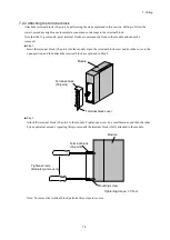
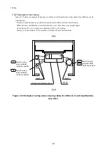
Note: For the actual RI/O-IF module and remote I/O station module, cables
cannot be attached on the terminal block from the right side.
The following figure shows cables attached from the right to make
the wiring easier to understand.
Содержание S10VE
Страница 1: ...User s Manual General Description SEE 1 001 A ...
Страница 2: ...User s Manual General Description ...
Страница 27: ...S 24 Revision History Revision No History revision details Issue date Remarks A New edition Oct 2019 ...
Страница 53: ...This page is intentionally left blank ...
Страница 59: ...This page is intentionally left blank ...
Страница 67: ...This page is intentionally left blank ...
Страница 75: ...This page is intentionally left blank ...
Страница 77: ...This page is intentionally left blank ...
Страница 103: ...This page is intentionally left blank ...
Страница 129: ...This page is intentionally left blank ...
Страница 295: ...This page is intentionally left blank ...
Страница 309: ...This page is intentionally left blank ...
Страница 341: ...This page is intentionally left blank ...
Страница 345: ...This page is intentionally left blank ...
Страница 475: ...This page is intentionally left blank ...
Страница 489: ...This page is intentionally left blank ...
Страница 505: ......
Страница 506: ...This page is intentionally left blank ...


