


648
21.6
Module Standby Function
21.6.1
Module Standby Timing
The module standby function can halt several of the on-chip supporting modules (SCI1, SCI0, 16-
bit timer, 8-bit timer, and A/D converter) independently in the power-down state. This standby
function is controlled by bits MSTPH2 to MSTPH0 in MSTCRH and bits MSTPL7 to MSTPL0 in
MSTCRL. When one of these bits is set to 1, the corresponding on-chip supporting module is
placed in standby and halts at the beginning of the next bus cycle after the MSTCR write cycle.
21.6.2
Read/Write in Module Standby
When an on-chip supporting module is in module standby, read/write access to its registers is
disabled. Read access always results in H'FF data. Write access is ignored.
21.6.3
Usage Notes
When using the module standby function, note the following points.
On-chip Supporting Module Interrupts: Before setting a module standby bit, first disable
interrupts by that module. When an on-chip supporting module is placed in standby by the
module standby function, its registers are initialized, including registers with interrupt request
flags.
Pin States: Pins used by an on-chip supporting module lose their module functions when the
module is placed in module standby. What happens after that depends on the particular pin. For
details, see section 7, I/O Ports. Pins that change from the input to the output state require special
care. For example, if SCI1 is placed in module standby, the receive data pin loses its receive data
function and becomes a port pin. If its port DDR bit is set to 1, the pin becomes a data output pin,
and its output may collide with external SCI transmit data. Data collision should be prevented by
clearing the port DDR bit to 0 or taking other appropriate action.
Register Resetting: When an on-chip supporting module is halted by the module standby
function, all its registers are initialized. To restart the module, after its MSTCR bit is cleared to 0,
its registers must be set up again. It is not possible to write to the registers while the MSTCR bit is
set to 1.
Содержание H8/3060
Страница 10: ......
Страница 16: ......
Страница 114: ...66 ...
Страница 132: ...84 ...
Страница 144: ...96 ...
Страница 170: ...122 ...
Страница 212: ...164 ...
Страница 268: ...220 ...
Страница 332: ...284 ...
Страница 396: ...348 ...
Страница 494: ...446 ...
Страница 698: ...650 ...
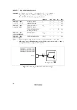
Страница 729: ...681 H8 3062F ZTAT or H8 3062F ZTAT R mask version Ports 1 2 5 LED 600 Ω Figure 22 5 Sample LED Circuit ...
Страница 748: ...700 H8 3064F ZTAT B mask version Ports 1 2 5 LED 600 Ω Figure 22 8 Sample LED Circuit ...
Страница 777: ...729 H8 3062F ZTAT B mask version Ports 1 2 5 LED 600 Ω Figure 22 14 Sample LED Circuit ...
Страница 810: ...762 ...
Страница 994: ...946 ...