287
9.1.2
Block Diagram
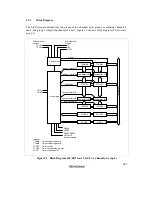
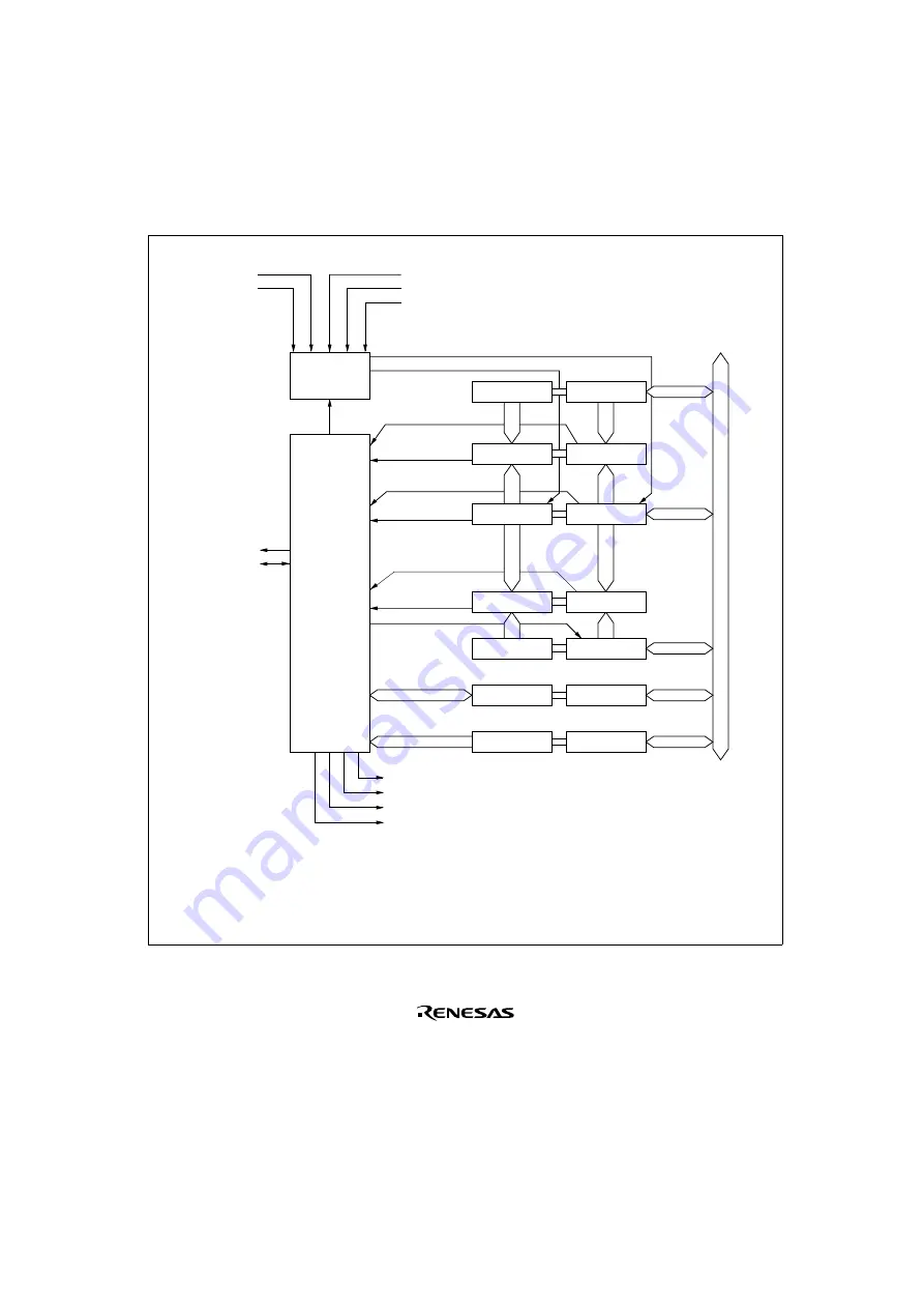
The 8-bit timers are divided into two groups of two channels each: group 0 comprising channels 0
and 1, and group 1 comprising channels 2 and 3. Figure 9.1 shows a block diagram of 8-bit timer
group 0.
φ
/8
φ
/64
φ
/8192
CMIA0
CMIB0
CMIA1/CMIB1
OVI0/OVI1
Interrupt signals
TMO
0
TMIO
1
TCORA0
TCORB0
8TCSR0
8TCR0
TCORA1
8TCNT1
TCORB1
8TCSR1
8TCR1
TCLKA
TCLKC
8TCNT0
Legend:
TCORA : Time constant register A
TCORB : Time constant register B
8TCNT : Timer counter
8TCSR : Timer control/status register
8TCR
: Timer control register
External clock
sources
Internal clock
sources
Clock select
Control logic
Clock 1
Clock 0
Compare match A1
Compare match A0
Overflow 1
Overflow 0
Compare match B1
Compare match B0
Input capture B1
Comparator A0
Comparator A1
Comparator B0
Comparator B1
Internal bus
Figure 9.1 Block Diagram of 8-Bit Timer Unit (Two Channels: Group 0)
Содержание H8/3060
Страница 10: ......
Страница 16: ......
Страница 114: ...66 ...
Страница 132: ...84 ...
Страница 144: ...96 ...
Страница 170: ...122 ...
Страница 212: ...164 ...
Страница 268: ...220 ...
Страница 332: ...284 ...
Страница 396: ...348 ...
Страница 494: ...446 ...
Страница 698: ...650 ...
Страница 729: ...681 H8 3062F ZTAT or H8 3062F ZTAT R mask version Ports 1 2 5 LED 600 Ω Figure 22 5 Sample LED Circuit ...
Страница 748: ...700 H8 3064F ZTAT B mask version Ports 1 2 5 LED 600 Ω Figure 22 8 Sample LED Circuit ...
Страница 777: ...729 H8 3062F ZTAT B mask version Ports 1 2 5 LED 600 Ω Figure 22 14 Sample LED Circuit ...
Страница 810: ...762 ...
Страница 994: ...946 ...


