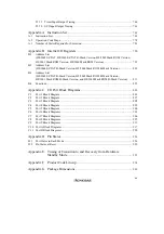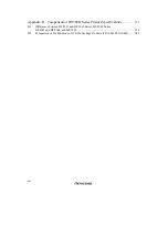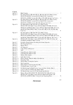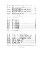
xx
Figure 8.17
Setup Procedure for Waveform Output by Compare Match (Example) ............ 255
Figure 8.18
0 and 1 Output (TOA = 1, TOB = 0).................................................................. 256
Figure 8.19
Toggle Output (TOA = 1, TOB = 0) .................................................................. 256
Figure 8.20
Output Compare Output Timing ........................................................................ 257
Figure 8.21
Setup Procedure for Input Capture (Example) ................................................... 258
Figure 8.22
Input Capture (Example) .................................................................................... 258
Figure 8.23
Input Capture Signal Timing.............................................................................. 259
Figure 8.24
Setup Procedure for Synchronization (Example) ............................................... 260
Figure 8.25
Synchronization (Example)................................................................................ 261
Figure 8.26
Setup Procedure for PWM Mode (Example) ..................................................... 262
Figure 8.27
PWM Mode (Example 1) ................................................................................... 263
Figure 8.28
PWM Mode (Example 2) ................................................................................... 264
Figure 8.29
Setup Procedure for Phase Counting Mode (Example)...................................... 265
Figure 8.30
Operation in Phase Counting Mode (Example).................................................. 266
Figure 8.31
Phase Difference, Overlap, and Pulse Width in Phase Counting Mode ............ 266
Figure 8.32
Timing for Setting 16-Bit Timer Output Level by Writing to TOLR ................ 267
Figure 8.33
Timing of Setting of IMFA and IMFB by Compare Match ............................... 268
Figure 8.34
Timing of Setting of IMFA and IMFB by Input Capture .................................. 269
Figure 8.35
Timing of Setting of OVF .................................................................................. 270
Figure 8.36
Timing of Clearing of Status Flags .................................................................... 270
Figure 8.37
Contention between 16TCNT Write and Clear.................................................. 272
Figure 8.38
Contention between 16TCNT Word Write and Increment ................................ 273
Figure 8.39
Contention between 16TCNT Byte Write and Increment.................................. 274
Figure 8.40
Contention between General Register Write and Compare Match .................... 275
Figure 8.41
Contention between 16TCNT Write and Overflow ........................................... 276
Figure 8.42
Contention between General Register Read and Input Capture ......................... 277
Figure 8.43
Contention between Counter Clearing by Input Capture and Counter
Increment............................................................................................................ 278
Figure 8.44
Contention between General Register Write and Input Capture........................ 279
Figure 9.1
Block Diagram of 8-Bit Timer Unit (Two Channels: Group 0) ......................... 287
Figure 9.2
8TCNT Access Operation (CPU Writes to 8TCNT, Word) .............................. 301
Figure 9.3
8TCNT Access Operation (CPU Reads 8TCNT, Word).................................... 301
Figure 9.4
8TCNT0 Access Operation (CPU Writes to 8TCNT0, Upper Byte) ................. 301
Figure 9.5
8TCNT1 Access Operation (CPU Writes to 8TCNT1, Lower Byte) ................ 302
Figure 9.6
8TCNT0 Access Operation (CPU Reads 8TCNT0, Upper Byte) ...................... 302
Figure 9.7
8TCNT1 Access Operation (CPU Reads 8TCNT1, Lower Byte)...................... 302
Figure 9.8
Count Timing for Internal Clock Input .............................................................. 303
Figure 9.9
Count Timing for External Clock Input (Both-Edge Detection)........................ 304
Figure 9.10
Timing of Timer Output ..................................................................................... 304
Figure 9.11
Timing of Clear by Compare Match .................................................................. 305
Figure 9.12
Timing of Clear by Input Capture ...................................................................... 305
Figure 9.13
Timing of Input Capture Input Signal ................................................................ 306
Figure 9.14
CMF Flag Setting Timing when Compare Match Occurs.................................. 306
Содержание H8/3060
Страница 10: ......
Страница 16: ......
Страница 114: ...66 ...
Страница 132: ...84 ...
Страница 144: ...96 ...
Страница 170: ...122 ...
Страница 212: ...164 ...
Страница 268: ...220 ...
Страница 332: ...284 ...
Страница 396: ...348 ...
Страница 494: ...446 ...
Страница 698: ...650 ...
Страница 729: ...681 H8 3062F ZTAT or H8 3062F ZTAT R mask version Ports 1 2 5 LED 600 Ω Figure 22 5 Sample LED Circuit ...
Страница 748: ...700 H8 3064F ZTAT B mask version Ports 1 2 5 LED 600 Ω Figure 22 8 Sample LED Circuit ...
Страница 777: ...729 H8 3062F ZTAT B mask version Ports 1 2 5 LED 600 Ω Figure 22 14 Sample LED Circuit ...
Страница 810: ...762 ...
Страница 994: ...946 ...

