476
16.1.1
Block Diagram
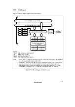
Figure 16.1 shows a block diagram of the on-chip RAM.
H'FEF20*
H'FEF22*
H'FFF1E*
H'FEF21*
H'FEF23*
H'FFF1F*
Internal data bus (upper 8 bits)
Internal data bus (lower 8 bits)
Bus interface
SYSCR
On-chip RAM
Even addresses
Odd addresses
Legend:
SYSCR: System control register
Note:
*
This example is of the H8/3062 mask ROM version operating in mode 7. The lower 20 bits
of the address are shown.
Figure 16.1 RAM Block Diagram
16.1.2
Register Configuration
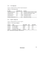
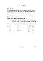
The on-chip RAM is controlled by SYSCR. Table 16.2 gives the address and initial value of
SYSCR.
Table 16.2
System Control Register
Address
*
Name
Abbreviation
R/W
Initial Value
H'EE012
System control register
SYSCR
R/W
H'09
Note:
*
Lower 20 bits of the address in advanced mode
Содержание H8/3060
Страница 10: ......
Страница 16: ......
Страница 114: ...66 ...
Страница 132: ...84 ...
Страница 144: ...96 ...
Страница 170: ...122 ...
Страница 212: ...164 ...
Страница 268: ...220 ...
Страница 332: ...284 ...
Страница 396: ...348 ...
Страница 494: ...446 ...
Страница 698: ...650 ...
Страница 729: ...681 H8 3062F ZTAT or H8 3062F ZTAT R mask version Ports 1 2 5 LED 600 Ω Figure 22 5 Sample LED Circuit ...
Страница 748: ...700 H8 3064F ZTAT B mask version Ports 1 2 5 LED 600 Ω Figure 22 8 Sample LED Circuit ...
Страница 777: ...729 H8 3062F ZTAT B mask version Ports 1 2 5 LED 600 Ω Figure 22 14 Sample LED Circuit ...
Страница 810: ...762 ...
Страница 994: ...946 ...

