500
17.5
Flash Memory Programming/Erasing
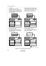
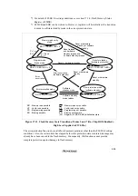
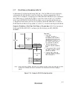
A software method, using the CPU, is employed to program and erase flash memory in the on-
board programming modes. There are four flash memory operating modes:
program mode, erase
mode, program-verify mode, and erase-verify mode. Transitions to these modes are made by
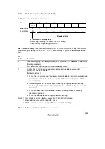
setting the PSU, ESU, P, E, PV, and EV bits in FLMCR.
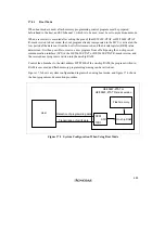
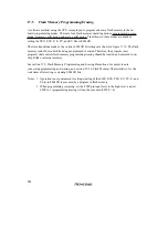
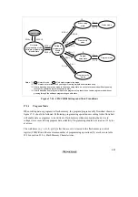
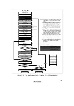
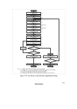
The state transitions made by the various FLMCR bit settings are shown in figure 17.10. The flash
memory cannot be read while being programmed or erased. Therefore, the program (user
program) that controls flash memory programming/erasing should be located and executed in on-
chip RAM or external memory.
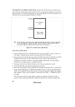
See section 17.9, Flash Memory Programming and Erasing Precautions, for points to note
concerning programming and erasing, and section 22.2.6, Flash Memory Characteristics, for the
wait times after setting or clearing FLMCR bits.
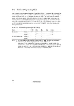
Notes: 1. Operation is not guaranteed if setting/clearing of the SWE, ESU, PSU, EV, PV, E, and
P bits in FLMCR is executed by a program in flash memory.
2. When programming or erasing, set the FWE pin input level to the high level, and set
FWE to 1 (programming/erasing will not be executed if FWE = 0).
Содержание H8/3060
Страница 10: ......
Страница 16: ......
Страница 114: ...66 ...
Страница 132: ...84 ...
Страница 144: ...96 ...
Страница 170: ...122 ...
Страница 212: ...164 ...
Страница 268: ...220 ...
Страница 332: ...284 ...
Страница 396: ...348 ...
Страница 494: ...446 ...
Страница 698: ...650 ...
Страница 729: ...681 H8 3062F ZTAT or H8 3062F ZTAT R mask version Ports 1 2 5 LED 600 Ω Figure 22 5 Sample LED Circuit ...
Страница 748: ...700 H8 3064F ZTAT B mask version Ports 1 2 5 LED 600 Ω Figure 22 8 Sample LED Circuit ...
Страница 777: ...729 H8 3062F ZTAT B mask version Ports 1 2 5 LED 600 Ω Figure 22 14 Sample LED Circuit ...
Страница 810: ...762 ...
Страница 994: ...946 ...

